Method of synchronizing servo timing in an optical wireless link

a technology of optical wireless link and synchronization method, which is applied in the direction of transmission monitoring, frequency-division multiplex, data switching network, etc., can solve the problems of reducing the phase margin, not always optimal configuration, and adverse effects on the control system, so as to improve the data processing efficiency and or control loop performance.

Active Publication Date: 2008-06-24
TEXAS INSTR INC
View PDF10 Cites 23 Cited by
  • Summary
  • Abstract
  • Description
  • Claims
  • Application Information

AI Technical Summary

Benefits of technology

[0008]In one aspect of the invention, a method is provided for synchronizing servos in an optical wireless communication link to improve data processing efficiency and or control loop performance.

Problems solved by technology

This asynchronous operating mode however, is not always an optimal configuration.
This delay can have adverse implications on the control system, such as, for example, decreasing the phase margin.

Method used


Image

  • Method of synchronizing servo timing in an optical wireless link
  • Method of synchronizing servo timing in an optical wireless link
  • Method of synchronizing servo timing in an optical wireless link

Examples


Embodiment Construction

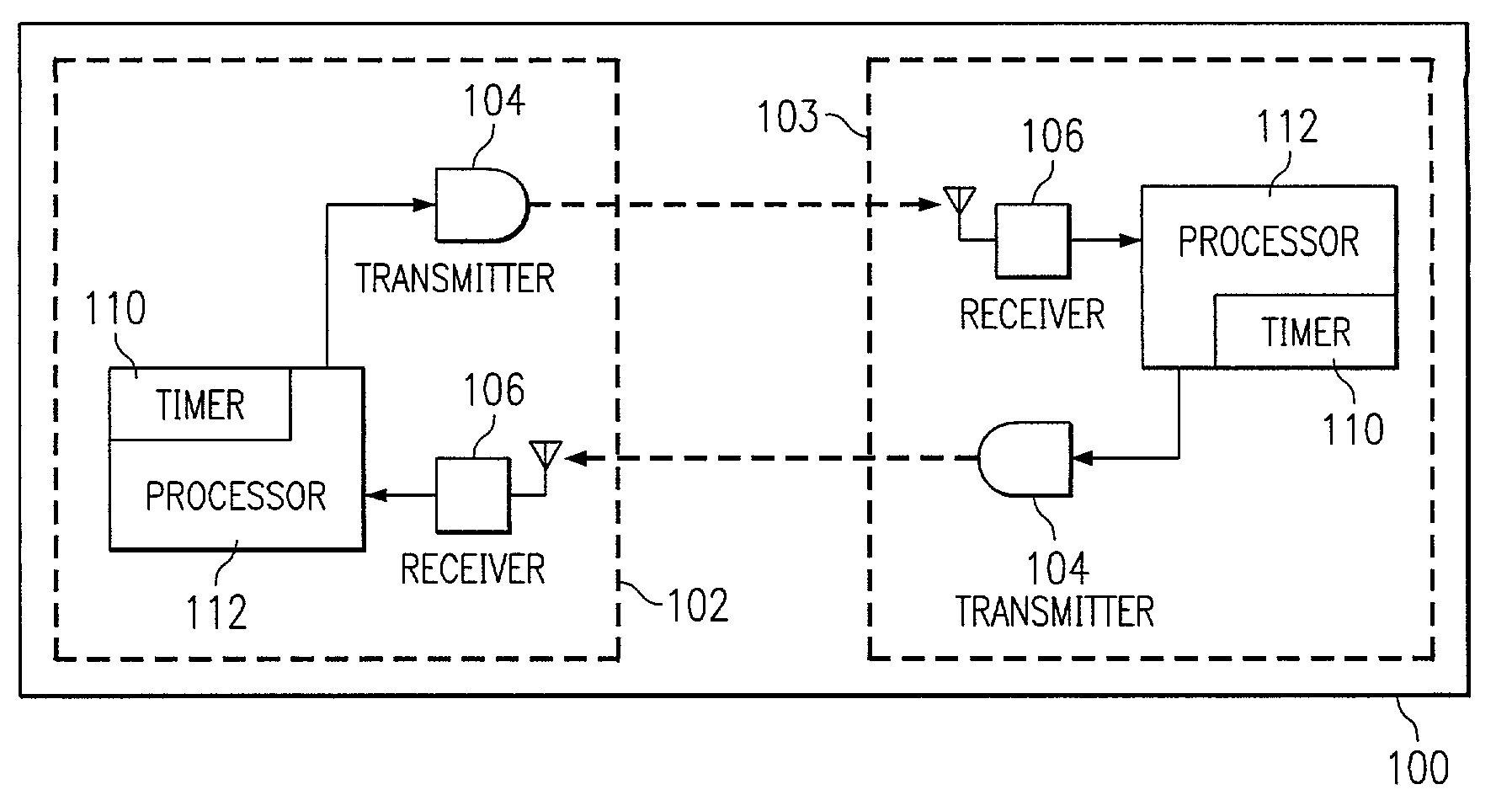
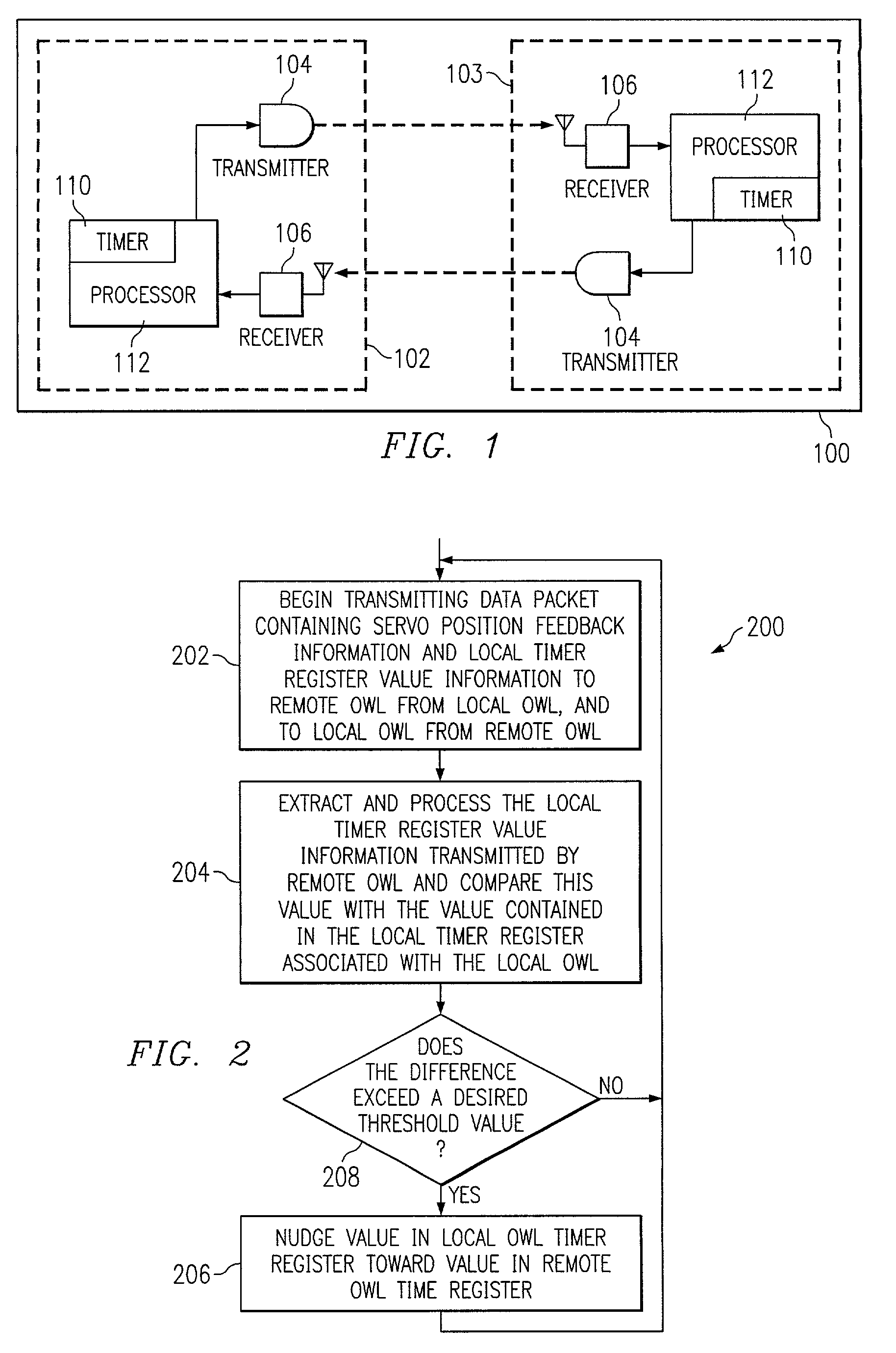
[0018]FIG. 1 is a block diagram illustrating an OWL system 100 having a pair of OWLs 102, 103 communicating with one another in which each OWL includes a transmitter 104, receiver 106 and a processor 112 including a local timer 110. The transmitter 104 is able to change the direction of its transmitted beam by known amounts of angular displacement. The receiver 106 sees this motion as a linear displacement, and sends position correction information back to the transmitter 104. This feedback is used by a servo control loop algorithm to position the transmitted beam on the receiver 106 of the remote station. U.S. patent application Ser. No. 10 / 060,549, entitled Calibration Method For Station Orientation, filed by Oettinger et al. on Jan. 30, 2002, discloses a method of calibrating station orientation in an OWL. The '549 patent application is assigned to the assignee of the present invention, and is hereby incorporated by reference in its entirety herein.

[0019]While both OWLs 102, 103 ...


PUM


Abstract

A technique for synchronizing the servo control systems between two optical wireless links (OWLs) that are in communication with one another. This synchronization allows the alignment in time of the various tasks to be assigned in a desired time period. The synchronization is not intended to synchronize the two OWLs down to the processor clock level, but rather at the servo sampling level, preferably to within a few percent of the servo sampling time. This synchronization may be advantageous in improving processor efficiency and control loop performance, and or improving system calibrations.

Description

BACKGROUND OF THE INVENTION[0001]1. Field of the Invention[0002]This invention relates generally to optical wireless communication links, and more particularly, to a method of synchronizing servo timing in an optical wireless link (OWL).[0003]2. Description of the Prior Art[0004]An optical wireless link system consists of two stations: Each of which contains an optical transmitter and an optical receiver. The transmitter is able to change the direction of its transmitted beam by known amounts of angular displacement. The receiver sees this motion and sends position correction information back to the transmitter. This feedback is used by a servo control loop to position the transmitted beam on the receiver of the remote station.[0005]While both OWL's have roughly equal sample periods, their servo systems generally operate in an asynchronous mode from one another. This asynchronous operating mode however, is not always an optimal configuration. When a position feedback packet is recei...

Claims


Application Information

Patent Timeline
Patent Type & Authority Patents(United States)
IPC IPC(8): H04B10/00H04L12/56
CPCH04J3/0664
Inventor OETTINGER, ERIC G.HEMINGER, MARK D.ANDERSON, TODD B.
Owner TEXAS INSTR INC
Why Eureka
Try Eureka