Online measurement method for welding line characteristic point positions and welding line trajectory automatic measurement system

A technology of welding seam characteristics and measurement methods, which is applied in the field of automatic welding seam trajectory measurement, can solve problems such as the failure of processing methods, and achieve the effect of accurate online automatic welding

Active Publication Date: 2019-01-11
SOUTH CHINA UNIV OF TECH
View PDF5 Cites 28 Cited by
  • Summary
  • Abstract
  • Description
  • Claims
  • Application Information

AI Technical Summary

Problems solved by technology

However, most of the existing algorithms use traditional morphology to process weld images, and use single geometric feature recognition algorithms or statistical decision-making to identify welds.
When the weld image is blocked by strong arc light and spatter, the pixel-level processing method will fail

Method used


Image

  • Online measurement method for welding line characteristic point positions and welding line trajectory automatic measurement system
  • Online measurement method for welding line characteristic point positions and welding line trajectory automatic measurement system
  • Online measurement method for welding line characteristic point positions and welding line trajectory automatic measurement system

Examples


Embodiment 1

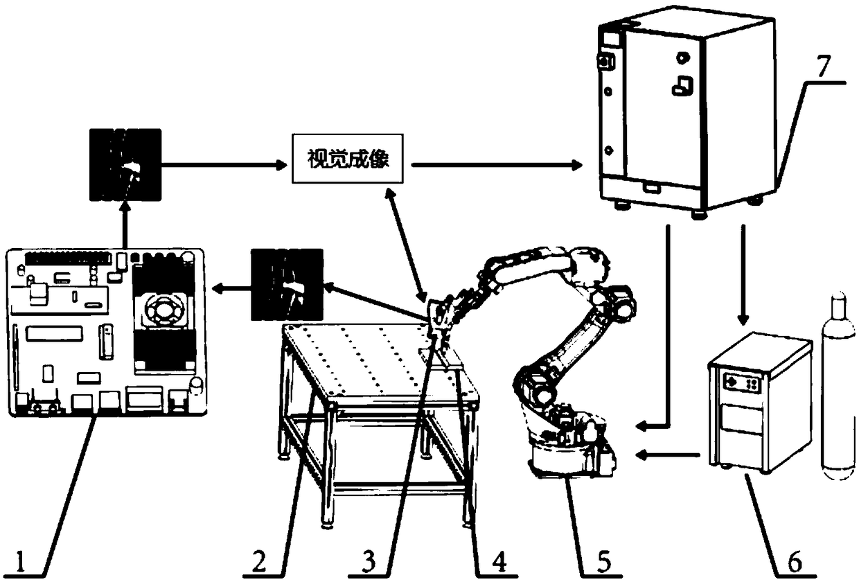
[0068] Such as Figure 1-3 As shown, an automatic measurement system for weld trajectory includes an embedded development board 1 , a laser vision sensor 3 , a welding robot 5 , a robot controller 7 , matching welding equipment 6 , and a workpiece clamping workbench 2 .

[0069] A welding torch is installed on the end flange of the welding robot through a fixing piece. The laser vision sensor is installed parallel to the welding torch in advance of the welding direction to extract the weld seam image information in real time. The robot controller provides control signals. The welding machine and supporting shielding gas are Welding provides energy and materials. The embedded development board is connected with the laser vision sensor via Ethernet. Accurate online automatic welding can be realized.

[0070] The workpiece clamping workbench in this embodiment includes an aluminum profile bracket and a support plate. The cross-sectional size of the aluminum profile bracket is 6...

Embodiment 2

[0075] Such as Figure 4 , 6 As shown, a method for online measurement of weld feature point position. Include steps:

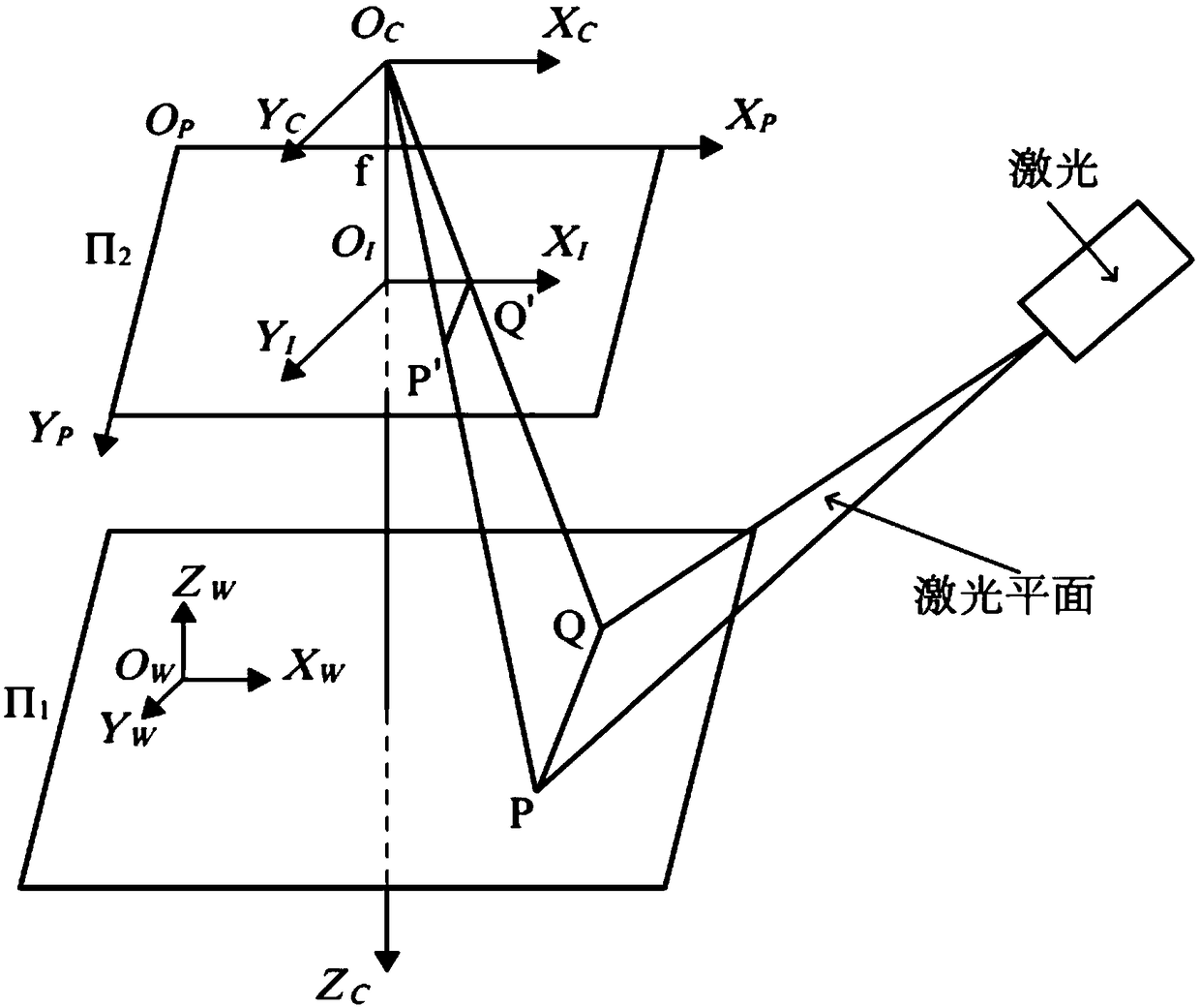
[0076] S1. Adjust the spatial position and posture of the welding robot so that the sharp point of the welding torch moves to the initial welding position, the laser line is irradiated obliquely on the workpiece, and the laser stripes representing the contour information of the weld must be within the field of vision;

[0077]S2. Before welding starts, the camera in the laser vision sensor collects the first frame of weld seam image without arc light, and sends it to the embedded development board TX2 by Ethernet, initializes the image information through the interactive program and manually locates the initial features point to get the starting position of the weld;

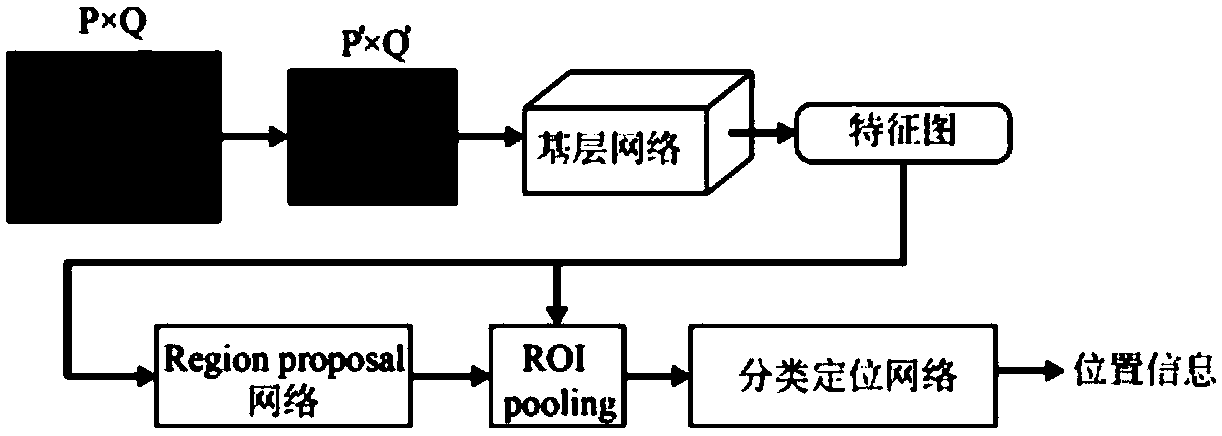
[0078] S3. After the welding starts, the camera of the laser vision sensor continuously collects weld seam images at a sampling frequency of 50 Hz, and sends them to the image processor thro...

Embodiment 3

[0102] Such as Figure 4-5 , 7, an online measurement method for the position of weld feature points. Include steps:

[0103] S1. Adjust the spatial position and posture of the welding robot so that the sharp point of the welding torch moves to the initial welding position, the laser line is obliquely irradiated on the workpiece, and the laser stripes representing the contour information of the weld must be within the field of vision.

[0104] S2. Before welding starts, the camera in the laser vision sensor collects the first frame of weld seam image without arc light, and sends it to the embedded development board TX2 by Ethernet, initializes the image information through the interactive program and manually locates the initial features point to get the starting position of the weld;

[0105] S3. After the welding starts, the camera of the laser vision sensor continuously collects weld seam images at a sampling frequency of 50 Hz, and sends them to the image processor throu...


PUM

PropertyMeasurementUnit
transmittivityaaaaaaaaaa

Abstract

The invention discloses an online measurement method for welding line characteristic point positions. The method comprises the following steps: a welding gun is positioned in an initial welding position; image information of welding line contours is initialized to obtain welding line initial positions; welding line images are acquired; welding line positions at present are predicted; the modelingof the welding line images in a time sequence direction is finished; characteristics of the welding line images are extracted; the tracking positioning of the welding line characteristics points is finally realized; and a motion trajectory of the welding gun is calculated. Meanwhile, the invention discloses a welding line trajectory automatic measurement system; and the system comprises an embedded development board, a laser visual sensor, a welding robot, a robot controller, mated welding equipment and a workpiece clamping worktable. The method can deal with the noise disturbance under non-structural welding environment, improves the robustness and the stability of a welding line tracking system, realizes automatic identification of welding line characteristic points, and greatly improvesthe automation degree and the production efficiency.

Description

technical field [0001] The invention relates to the field of automatic measurement of weld trajectory, in particular to an on-line measurement method of weld characteristic point positions combined with target detection and tracking algorithms and an automatic measurement system for weld trajectory. Background technique [0002] Welding plays a very important role in the manufacturing process. With the development of automation technology, welding robots have become the main welding automation equipment. Welding robots usually adopt the working mode of teaching and reproduction, that is, guide the robot through the user, and let the robot memorize the position, posture, motion parameters, etc. of each movement taught during the process, and then automatically generate a continuous execution of all operations. program of. After the teaching is completed, you only need to give the robot a start command, and the robot will repeat the expected welding work through the working ...

Claims


Application Information

Patent Timeline
Patent Type & Authority Applications(China)
IPC IPC(8): B23K9/127B25J9/16
CPCB23K9/1274B25J9/1697Y02P90/30
Inventor 邹焱飚蓝睿
Owner SOUTH CHINA UNIV OF TECH
Why Eureka
Try Eureka