
Controlled self-ignition of an otto engine by supporting spark ignition

a self-ignition and spark ignition technology, applied in the direction of electric control, machines/engines, mechanical equipment, etc., can solve the problems of complex regulation of the combustion process and especially the control of the self-ignition of the mixture, the inability to meet the needs of stratified operation, and the inability to uniformly distribute the fuel in the combustion chamber

Inactive Publication Date: 2008-07-01
ROBERT BOSCH GMBH
View PDF7 Cites 0 Cited by
  • Summary
  • Abstract
  • Description
  • Claims
  • Application Information

AI Technical Summary

Benefits of technology

The present invention is about a method for controlling and regulating self-ignition in an internal combustion engine. This is achieved by introducing a fuel-air mixture into a combustion chamber and compressing it during the compression stroke. A flame front is generated by spark ignition, which compresses and / or heats up the remaining fuel-air mixture, and the latter is converted to intermediate combustion products. This method allows for control and regulation of self-ignition at different load points by using a stratified injection in combination with spark ignition. The invention also involves the use of a negative valve overlap to retain exhaust gas in the combustion chamber, which can influence the combustion process. The technical effects of this invention include improved engine performance and efficiency, as well as better control and regulation of combustion timing.

Problems solved by technology

In the case of both combustion methods there is no uniform fuel distribution present in the combustion chamber, but rather a stratified charge.
Greater loads, however, cannot be satisfied by stratified operation.
To be sure, the regulation of the combustion process and especially the control of the self-ignition of the mixture is complex.

Method used


Image

  • Controlled self-ignition of an otto engine by supporting spark ignition
  • Controlled self-ignition of an otto engine by supporting spark ignition
  • Controlled self-ignition of an otto engine by supporting spark ignition

Examples


Embodiment Construction

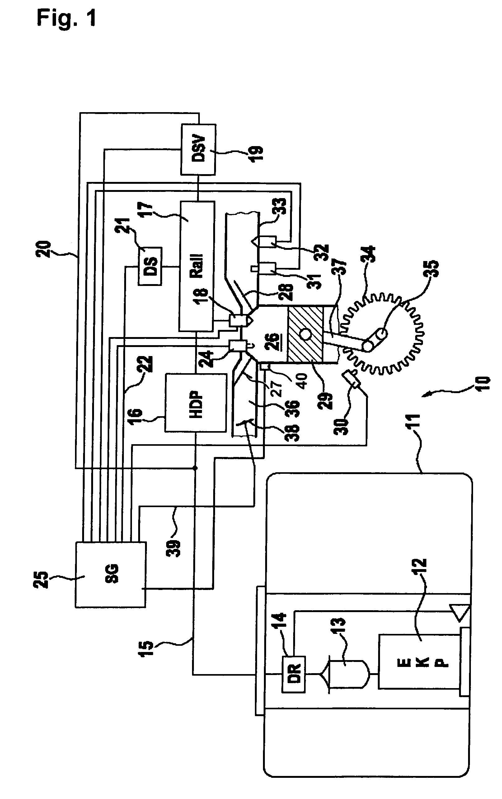
[0018]FIG. 1 shows a schematic representation of a cylinder of an internal combustion engine having appertaining components of the fuel supply system. Shown in exemplary form is an internal combustion engine having direct injection (Otto engine using direct gasoline injection BDE) having a fuel tank 11 at which an electric fuel pump (EKP) 12, a fuel filter 13 and a low pressure controller 14 are situated. From fuel tank 11, a fuel line 15 goes to a high pressure pump 16. A storage space 17 follows high pressure pump 16. Fuel injectors 18 are situated at storage space 17, which are preferably directly assigned to combustion chambers 26 of the internal combustion engine. In the case of internal combustion engines having direct injection, at least one fuel injector 18 is allotted to each combustion chamber 26, but, in this instance, a plurality of fuel injectors 18 may also be provided for each combustion chamber 26. The fuel is conveyed by electric fuel pump 12 from fuel tank 11, via ...


PUM


Abstract

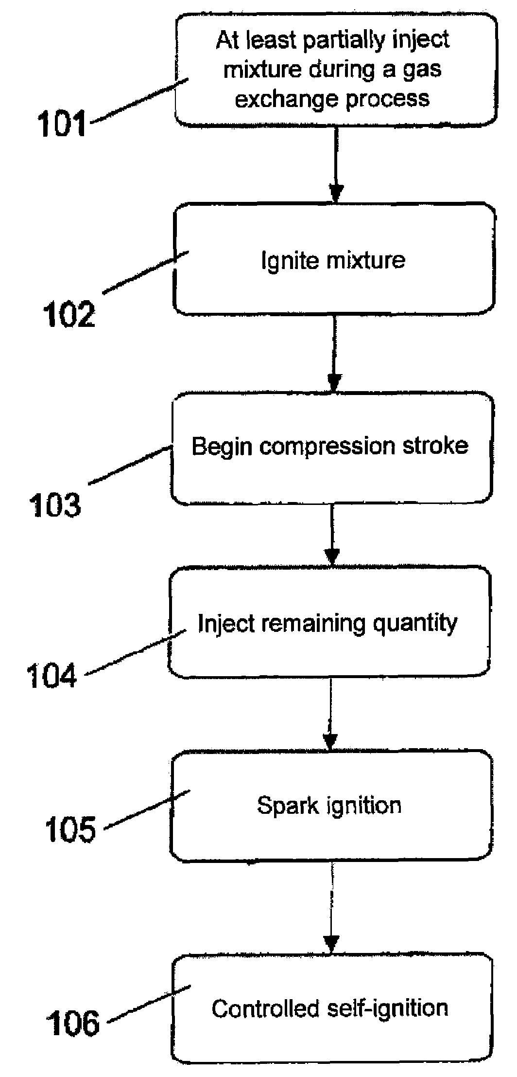
A method for operating an internal combustion engine in controlled self-ignition, a fuel-air mixture being introduced into a combustion chamber at least partially in a gas-exchange cycle, and being compressed in a compression stroke, the load range usable for the Otto engine self-ignition is broadened in that, in the fuel-air mixture, during the gas-exchange cycle, a flame front is generated at one or a plurality of places by spark ignition, which compresses and / or heats up the remaining fuel-air mixture, and converts the latter thereby at least partially to intermediate combustion products.

Description

FIELD OF THE INVENTION[0001]The present invention relates to a method for operating an internal combustion engine in controlled self-ignition, a fuel-air mixture being introduced at least partially in a gas-exchange cycle in a combustion chamber, and being compressed in a compression stroke, as well as an internal combustion engine operating according to the method.BACKGROUND INFORMATION[0002]In direct injection gasoline internal combustion engines known from the related art, gasoline is injected directly into the combustion chamber of a cylinder of the internal combustion engine. The gasoline-air mixture compressed in the combustion chamber is then ignited by the ignition from an ignition spark in the combustion chamber. The volume of the ignited gasoline-air mixture expands explosively and sets in motion a piston that is able to move back and forth in the cylinder. The back and forth motion of the piston is transmitted to a crankshaft of the internal combustion engine.[0003]Direct...

Claims


Application Information

Patent Timeline
Patent Type & Authority Patents(United States)
IPC IPC(8): F02B23/08F02B17/00F02P23/04
CPCF02B1/06F02B9/06F02D41/3041F02P23/04F02D2041/001F02D41/006F02D41/402Y02T10/40
Inventor KULZER, ANDRE-FRANCISCO CASAL
Owner ROBERT BOSCH GMBH
Learn More