Hollow-fiber spinning nozzle

a technology of hollow fiber and nozzle, which is applied in the direction of spinnerette packs, dough shaping, cocoa, etc., can solve the problems of limiting the precision of the underlying lithography mask which is used, and achieve the effect of minimizing production tolerances

Inactive Publication Date: 2008-07-01
FRESENIUS MEDICAL CARE DEUTSCHLAND GMBH
View PDF16 Cites 11 Cited by
  • Summary
  • Abstract
  • Description
  • Claims
  • Application Information

AI Technical Summary

Benefits of technology

[0006]It is therefore the object of the invention to provide hollow fiber spinning nozzles with which fine capillary membranes can also be manufactured, with the production tolerances being minimized and the manufacturing process for these hollow fiber spinning nozzles being made much cheaper.

Problems solved by technology

It is only restricted by the precision of the underlying lithography mask which is used in microstructure technology.

Method used


Image

  • Hollow-fiber spinning nozzle
  • Hollow-fiber spinning nozzle
  • Hollow-fiber spinning nozzle

Examples


Embodiment Construction

[0024]Further scope of applicability of the present invention will become apparent from the detailed description given hereinafter. However, it should be understood that the detailed description and specific examples, while indicating preferred embodiments of the invention, are given by way of illustration only, since various changes and modifications within the spirit and scope of the invention will become apparent to those skilled in the art from this detailed description.

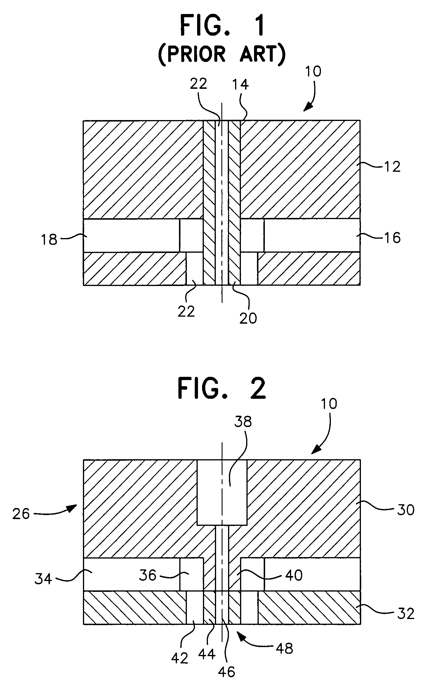
[0025]In FIG. 2, a hollow fiber spinning nozzle 10 in accordance with a first aspect of the invention is shown. Here, the total base body 26 is put together from two single plates 30 and 32. In the first plate 30, mass supply passages 34, a mass flow homogenization zone 36, a coagulation agent supply bore 38 and a needle stub 40 are formed by a corresponding etching process which will be described in detail later. The three-dimensional design of the hollow fiber spinning nozzle shown here in FIG. 2 results from F...


PUM

PropertyMeasurementUnit
outer diameteraaaaaaaaaa
inner diameteraaaaaaaaaa

Abstract

A hollow fiber spinning nozzle in which supply bores and a nozzle structure connected to these and having a mass discharge opening and a needle with a coagulation agent bore are formed in a base body. At least two plate-shaped bodies structured by means of micro-structure technology are joined together to form the base body.

Description

[0001]This is a nationalization of PCT / EP03 / 01447 filed Feb. 13, 2003 and published in German.BACKGROUND OF THE INVENTION[0002]1. Field of the Invention[0003]The invention relates to a hollow fiber spinning nozzle in which coagulation agent / support agent passages and mass supply passages and a nozzle structure connected to these and having a mass discharge opening and a needle with a coagulation agent / support agent bore are formed in a base body.[0004]2. Description of the Related Art[0005]Hollow fiber spinning nozzles are already known which serve the manufacture of polymeric hollow fiber membranes. As shown in FIG. 1 in accordance with the enclosed drawing, such hollow fiber spinning nozzles 10 consist of a base body 12 made of metal into which a plurality of bores 14, 16, 18, 22 have been introduced. A tube 20 has been fitted into the bore 14 and a coagulation agent passage or a support agent passage 22 has been formed therein for the introduction of the coagulation agent or supp...

Claims


Application Information

Patent Timeline
Patent Type & Authority Patents(United States)
IPC IPC(8): D01D5/24D01D5/34B29C48/30D01D4/02
CPCD01D4/022D01D5/24D01D5/34Y10T156/1052Y10T29/4998Y10T29/49432Y10S425/217
Inventor KELLER, TORSTENSTAHL, JENS-HOLGER
Owner FRESENIUS MEDICAL CARE DEUTSCHLAND GMBH
Why Eureka
Try Eureka