Supercharge Your Innovation With Domain-Expert AI Agents!

Method of manufacturing suspension structure and chamber

a manufacturing method and suspension technology, applied in the manufacture of microstructured devices, microstructured technology, electric devices, etc., can solve the problems of broken structure layer or suspension part sticking to the substrate surface, difficult prior art methods to design and manufacture suspension structures, etc., to improve process yield and reduce costs.

Inactive Publication Date: 2008-07-01
TOUCH MICRO SYST TECH
View PDF4 Cites 2 Cited by
  • Summary
  • Abstract
  • Description
  • Claims
  • Application Information

AI Technical Summary

Benefits of technology

"The present invention provides a method of manufacturing a suspension structure and chamber that improves process yield and reduces cost. The method involves forming a sacrificial layer on a substrate, exposing a part of the substrate and the sacrificial layer, removing the sacrificial layer and the structure layer above it, and then removing the sacrificial layer in order to make the structure layer and sacrificial layer become the suspension structure and the chamber on the substrate."

Problems solved by technology

The suspended structure is applied in many MEMS devices such as a MEMS switch, an inkjet nozzle, and micro-microphones, etc., but the method of manufacturing a suspension structure according to the prior art still has many limitations.
Therefore, the prior art has to use specific metal that is not able to be etched by the KOH etching liquid, or form extra passivation layers and adhesive layers above and under the structure layer respectively.
Second, since the prior art uses the wet etching process to remove the semiconductor substrate to form a chamber in the semiconductor substrate, the suspension structure will be affected by the surface tension of the etching liquid, which results in a broken structure layer or the suspension part sticking to the substrate surface.
Third, it is very difficult for the prior art methods to design and manufacture the suspension structure and chamber with various shapes by adjusting the process parameters.

Method used


Image

  • Method of manufacturing suspension structure and chamber
  • Method of manufacturing suspension structure and chamber
  • Method of manufacturing suspension structure and chamber

Examples


Embodiment Construction

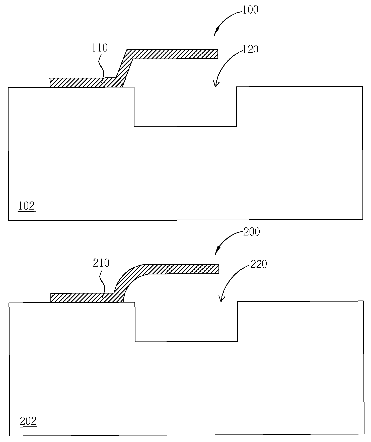
[0015]Please refer to FIG. 5 to FIG. 9. FIG. 5 to FIG. 9 shows the method of manufacturing a suspension structure and chamber in accordance with the first preferred embodiment of the present invention. As shown in FIG. 5, a hole 103 is formed on the substrate 102 first, and a first patterned photoresist layer 104 is formed on the substrate 102, wherein the substrate 102 can be a silicon wafer or a SOI, but is not limited to this. The method of forming the hole 103 can include a wet etching process, a sputtering etching process, a plasma etching process, or a reactive ion etching (RIE) process, and the shape of the hole 103 can be a semicircle, semi-ellipse, trapezoid, rectangle, trapezoid with round corners, or rectangle with round corners by adjusting the process parameters to meet the requirement of different MEMS devices.

[0016]Next, as shown in FIG. 6, since the photoresist will be fluid and then hardened after being heated, the first patterned photoresist layer 104 is heated to ...


PUM


Abstract

A method of manufacturing a suspension structure including providing a substrate, forming a hole and a sacrificial layer filling the hole on the substrate, forming a patterned photoresist layer on the substrate and the sacrificial layer, the patterned photoresist layer exposing a part of the substrate and the sacrificial layer, forming a structure layer on the substrate, the patterned photoresist layer, and the sacrificial layer, performing a lift off process to remove the patterned photoresist layer and the structure layer above the photoresist pattern, and performing a dry etch process to remove the sacrificial layer in order to make the structure layer and the hole become the suspension structure and the chamber.

Description

BACKGROUND OF THE INVENTION[0001]1. Field of the Invention[0002]The present invention relates to a method of manufacturing a suspension structure and chamber, and more particularly, to a method of manufacturing a suspension structure and chamber using a sacrificial layer, dry etching process, and lift off process.[0003]2. Description of the Prior Art[0004]Micro-electromechanical systems (MEMS) are modern technology, which coordinate electrical circuits and mechanics. MEMS have been applied to fabricate devices with both electrical circuits and mechanical elements, such as pressure sensors, accelerators, and micro-microphones. The suspended structure is applied in many MEMS devices such as a MEMS switch, an inkjet nozzle, and micro-microphones, etc., but the method of manufacturing a suspension structure according to the prior art still has many limitations.[0005]Please refer to FIG. 1 to FIG. 4. FIG. 1 to FIG. 4 shows the method of manufacturing a suspension structure and chamber by...

Claims


Application Information

Patent Timeline
Patent Type & Authority Patents(United States)
IPC IPC(8): H01L21/44
CPCB81C1/0015
Inventor KANG, YU-FU
Owner TOUCH MICRO SYST TECH
Features
  • R&D
  • Intellectual Property
  • Life Sciences
  • Materials
  • Tech Scout
  • Unparalleled Data Quality
  • Higher Quality Content
  • 60% Fewer Hallucinations
Learn More