Re-configurable amplifier protection apparatus and method

a protection apparatus and amplifier technology, applied in amplifier protection circuit arrangements, amplifiers with semiconductor devices only, semiconductor devices/discharge tubes, etc., can solve problems such as failure conditions, system run inefficiently, and protect itself from permanent damag

Active Publication Date: 2008-07-01
PIONEER CORP
View PDF8 Cites 7 Cited by
  • Summary
  • Abstract
  • Description
  • Claims
  • Application Information

AI Technical Summary

Benefits of technology

[0020]The present invention is for an amplifier, which is able to re-configure its internal protection circuits based on an output signal level. This allows the amplifier to apply the best protection level to the present operational condition. The protection level or threshold for protecting the amplifier is dynamically adjusted to a lower threshold level, thereby making it more sensitive in certain operating scenarios.

Problems solved by technology

When the threshold is exceeded a protection circuit is invoked, which shuts down the amplifier or otherwise causes it to protect itself from permanent damage.
The problem with currently available protection techniques is that fault conditions also occur in scenarios where the protection threshold is not exceeded.
In this case, the system runs inefficiently, so a large current being carried through the system may be a problem.
However, a short circuit condition, when it occurs at a time when the output voltage is low, may be a problem.
This causes the system to run inefficiently.
Moreover, during this condition the current will not be high enough to reach prior art protection thresholds, so the system will not shut down.
Since the system is running inefficiently in the latter short circuit condition and will not shut down, and at the same time sourcing a high current, the system components overheat, and / or become damaged.
In many of these cases the eventual destruction of the amplifier will occur due to excess power dissipation in the amplifier output section.
For example, if the speaker output is shorted during a low output level or low volume, the amplifier might not reach its protection level and never invoke the protection circuit.
Therefore, the amplifier will continue to operate in this fault condition, which may cause excessive power dissipation within the amplifier and its failure, despite having a protection circuit with a protection threshold in place.

Method used


Image

  • Re-configurable amplifier protection apparatus and method
  • Re-configurable amplifier protection apparatus and method
  • Re-configurable amplifier protection apparatus and method

Examples


Embodiment Construction

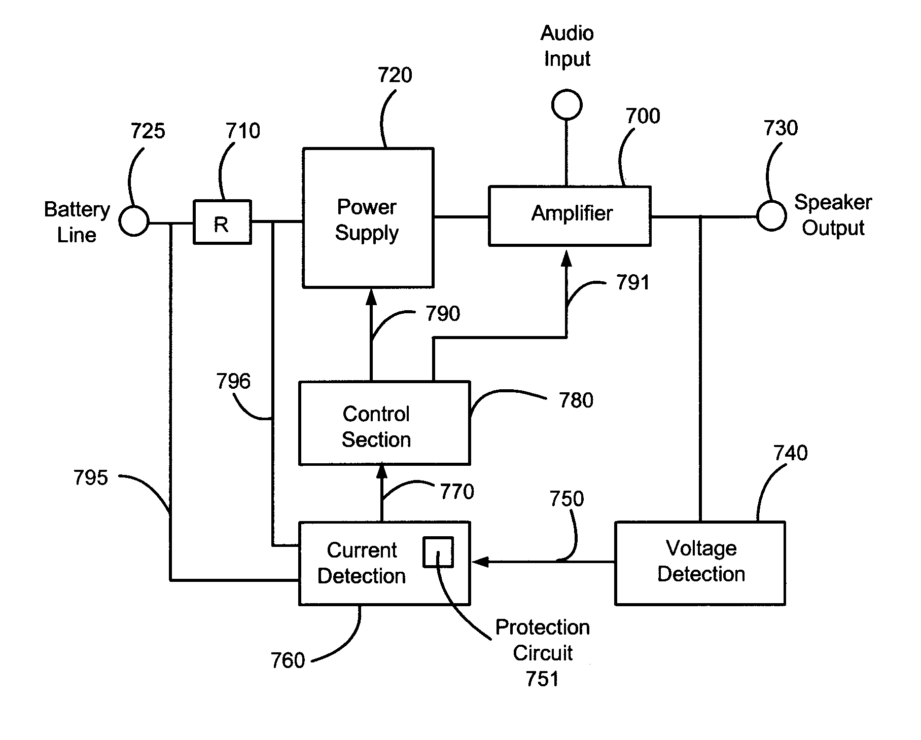
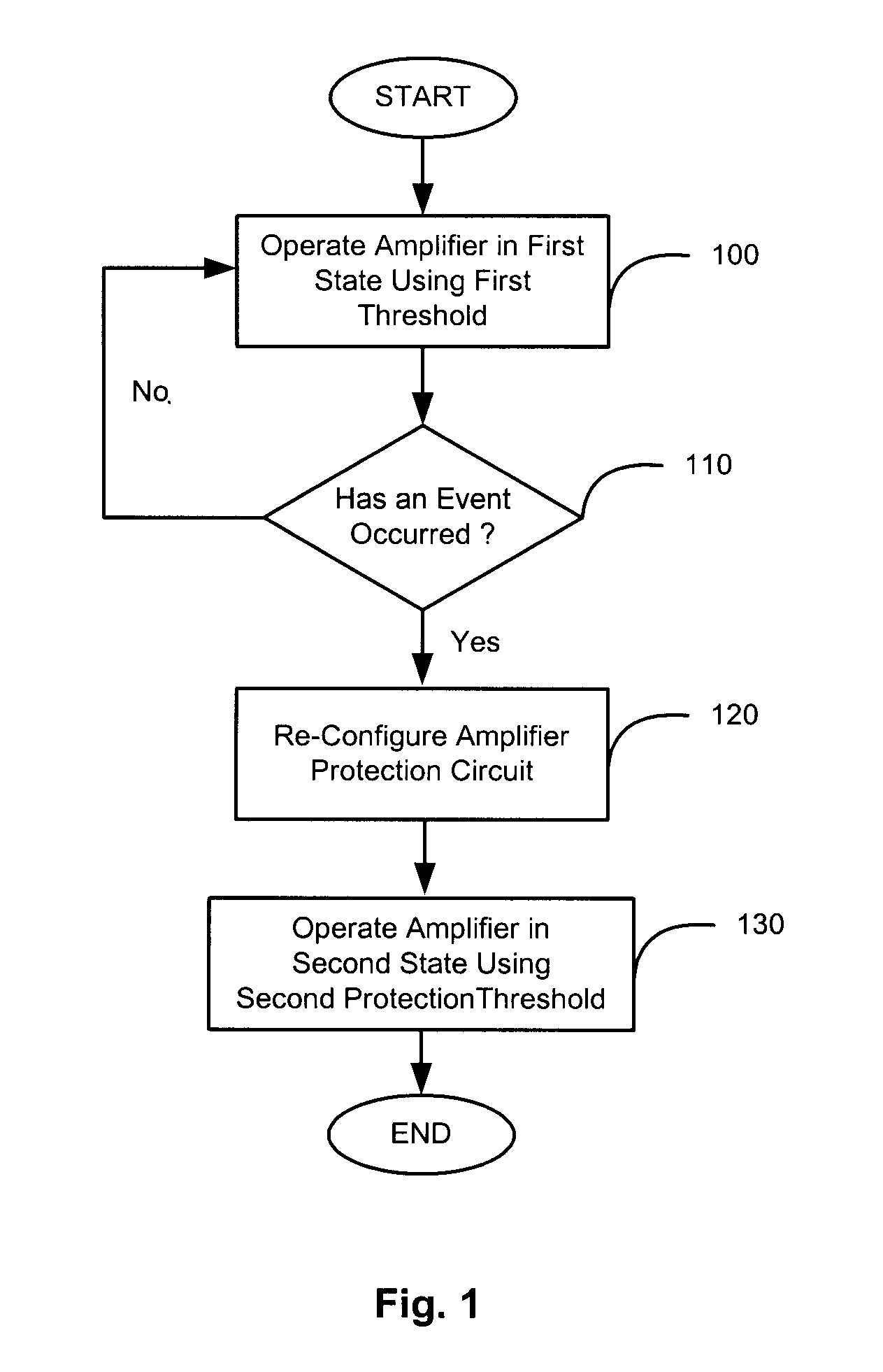
[0022]The present invention is directed to an amplifier, which is able to re-configure its internal protection circuits based on an output signal level. This allows the amplifier to apply the best protection level to the present operational condition. The protection level or “threshold” for protecting the amplifier is dynamically adjusted to a lower threshold level, thereby making it more sensitive in certain operating scenarios.

[0023]The protection circuitry of the present invention avoids problems with phase relationship and is compatible, for instance, with Class-D amplifiers. In one aspect of the invention, the circuitry measures the output signal as an average, which makes it easier to compare to references. In another aspect of the invention, the sensitivity of the circuitry changes in discrete intervals, which readily allows the use of references for control. In yet another aspect of the invention, current is measured on the battery input line, which is a low voltage.

[0024]FI...


PUM


Abstract

The present invention is directed to an amplifier, which is able to re-configure its internal protection circuits based on an output signal level. This allows the amplifier to apply the best protection level to the present operational condition. The protection level or threshold for protecting the amplifier is dynamically adjusted to a lower threshold level, thereby making it more sensitive in certain operating scenarios. In one embodiment of the present invention, a first current protection threshold is used to operate an amplifier in a first state. If an event occurs, the amplifier protection circuit is re-configured and the amplifier continues to operate with a second protection threshold in a second state.

Description

CROSS-REFERENCE TO RELATED APPLICATIONS[0001]This application herein incorporates by reference and claims the benefit of U.S. Provisional Application Ser. No. 60 / 628,193, filed on Nov. 15, 2004, entitled Dynamic Amplifier Protection (DAP) Technology.NOTICE OF MATERIAL SUBJECT TO COPYRIGHT PROTECTION[0002]All of the material in this patent document is subject to copyright protection under the copyright laws of the United States and of other countries. Portions of the material in this patent document are also subject to protection under the maskwork registration laws of the United States and of other countries. The owner of the copyright and maskwork rights has no objection to the facsimile reproduction by anyone of the patent document or the patent disclosure, as it appears in the United States Patent and Trademark Office file or records, but otherwise reserves all copyright and maskwork rights whatsoever.BACKGROUND OF THE INVENTION[0003]1. Field of the Invention[0004]The present inv...

Claims


Application Information

Patent Timeline
Patent Type & Authority Patents(United States)
IPC IPC(8): H03F1/14H03F1/52
CPCH03F1/52
Inventor SCHOENBERGER, MICHAEL A.
Owner PIONEER CORP
Why Eureka
Try Eureka