Magnetoresistance device with a diffusion barrier between a conductor and a magnetoresistance element and method of fabricating the same

a magnetoresistance element and diffusion barrier technology, applied in the field of magnetoresistance devices and methods of fabricating the same, can solve the problems of thermal stability, interdiffusion between hard and soft ferromagnetic layers, reduction of coercive forces of free ferromagnetic layers, etc., and achieve the effect of improving the thermal stability of a magnetoresistance elemen

Active Publication Date: 2008-07-01
NEC CORP
View PDF40 Cites 30 Cited by
  • Summary
  • Abstract
  • Description
  • Claims
  • Application Information

AI Technical Summary

Benefits of technology

[0023]An object of the present invention is to provide a technology for further improving thermal stability of a magnetoresistance element.
[0024]Another object of the present invention is to provide a technology for further improving thermal stability of a magnetoresistance element through preventing interdiffusion between layers incorporated within the magnetoresistance element and a conductor (such as a via contact and an interconnection) that electrically connects the magnetoresistance element with other elements.
[0025]Still another object of the present invention is to provide a technology for preventing a phenomenon in which a resistivity of a conductor that provides electrical connections between a magnetoresistance element and other elements is increased by diffusion of material included in layers incorporated within the magnetoresistance element, especially nickel and manganese, into the conductor.

Problems solved by technology

One of the issues of magnetoresistance elements is thermal stability.
Patent document 1 presents a problem concerning interdiffusion between hard and soft ferromagnetic layers.
Another issue of magnetoresistance elements is reduction in coercive forces of free ferromagnetic layers.
A free ferromagnetic layer composed of a layered structure including hard and soft ferromagnetic layers may not have the coercive force reduced sufficiently in the case that an increased MR ratio is required.
Firstly, the diffusion of material included in the conductor into the magnetic tunnel junction reduces the MR ratio thereof.
For a conductor including aluminum, diffusion of aluminum into the magnetic tunnel junction is especially serious, because aluminum is diffused by applying relatively low temperature.
Secondly, the diffusion of material included in the magnetoresistance element into the conductor, which electrically connects the magnetoresistance element with other elements, increases the resistance of the conductor.
Thirdly, thermal diffusion of material of the free ferromagnetic layer into the conductor that electrically connects the free ferromagnetic layer with other elements makes it difficult to achieve reduction in the coercive force through reducing the thickness t of the free ferromagnetic layer.
These samples exhibit poor repeatability.

Method used


Image

  • Magnetoresistance device with a diffusion barrier between a conductor and a magnetoresistance element and method of fabricating the same
  • Magnetoresistance device with a diffusion barrier between a conductor and a magnetoresistance element and method of fabricating the same
  • Magnetoresistance device with a diffusion barrier between a conductor and a magnetoresistance element and method of fabricating the same

Examples


example 1 (

The Present Invention)

substrate / Ta(3 nm) / AlCu(50 nm) / Ta(3 nm) / Al2O3(1 nm) / Ta(3 nm) / Ni81Fe19(3 nm) / IrMn(10 nm) / Co90Fe10(6 nm) / AlOx(2 nm) / Co90Fe10(2.5 nm) / Ni81Fe19(7.5 nm) / Al2O3(1 nm) / Ta(5 nm) / AlCu(300 nm)

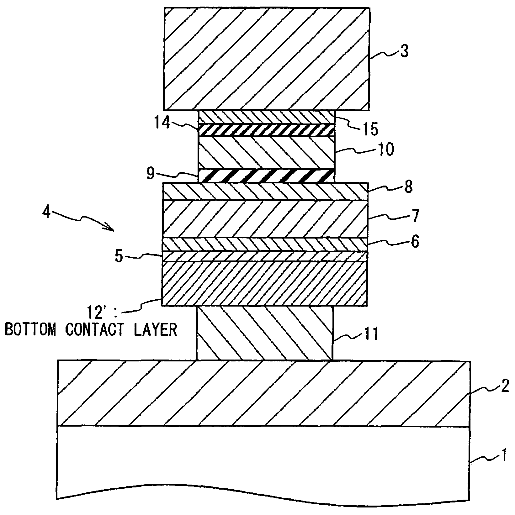
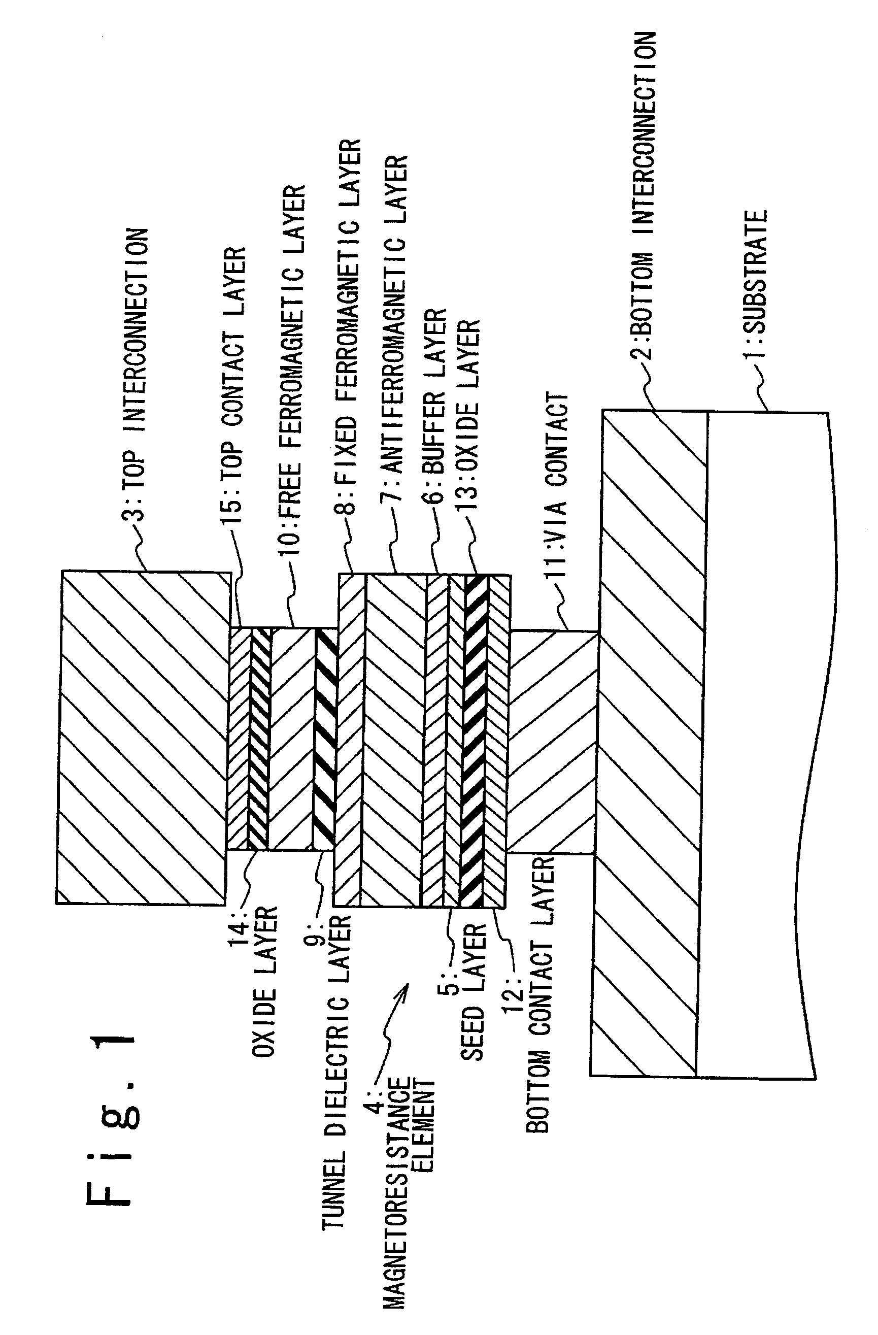
[0188]Comparative Example 1 corresponds with the structure shown in FIG. 1 with the oxide layers 13 and 14 omitted. Example 1 corresponds with the structure shown in FIG. 1, having the oxide layers 13 and 14 formed with Al2O3 of 1 nm in thickness. The AlCu layer of 50 nm in thickness corresponds with the bottom interconnection 2, while the AlCu layer of 300 nm in thickness corresponds with the top interconnection 3.

[0189]FIG. 19 illustrates changes in MR ratios of Comparative Example 1 and Example 1 depending on the thermal treatment temperature. Comparative Example 1 experience reduction in the MR ratio after the thermal treatment at the temperatures over 300° C., while Example 1 is resistant to the thermal treatment at or below 300° C., and experiences minor reduction after the the...

example 2 (

The Present Invention)

substrate / Ta(3 nm) / AlCu(50 nm) / Ta(3 nm) / Al2O3(1 nm) / Ta(3 nm) / Ni81Fe19(3 nm) / IrMn(10 nm) / Co90Fe10(4 nm), and

example 3 (

The Present Invention)

substrate / Ta(3 nm) / AlCu(50 nm) / Ta(3 nm) / MgO(1 nm) / Ta(3 nm) / Ni81Fe19(3 nm) / IrMn(10 nm) / Co90Fe10(4 nm)

[0191]Comparative Example 2 corresponds with a portion of the structure of FIG. 1 between the tunnel dielectric layer 9 and the substrate 1 with the oxide layer 13 omitted. Example 2 corresponds a portion of the structure of FIG. 1 between the tunnel dielectric layer 9 and the substrate 1, having the oxide layer 13 formed with Al2O3 of 1 nm in thickness. Example 3 corresponds a portion of the structure of FIG. 1 between the tunnel dielectric layer 9 and the substrate 1, having the oxide layer 13 formed with MgO of 1 nm in thickness. For all the samples, the AlCu layers of 50 nm in thickness correspond with the bottom electrodes 2.

[0192]FIG. 20 illustrates changes in sheet resistances of the AlCu layers depending on the thermal treatment temperature obtained from Comparative Example 2 and Example 2. Comparative Example 2, which does not include the oxide layer 13,...


PUM

PropertyMeasurementUnit
thicknessaaaaaaaaaa
thicknessesaaaaaaaaaa

Abstract

A magnetoresistance device is provided for improving thermal stability of a magnetoresistance element by preventing inter-diffusion between a conductor (such as a via and an interconnection) for connecting the magnetoresistance element to another element and layers constituting the magnetoresistance element. A magnetoresistance device is composed of a magnetoresistance element, a non-magnetic conductor providing electrical connection between said magnetoresistance element to another element, and a diffusion barrier structure disposed between the conductor and said magnetoresistance element, the magnetoresistance element including a free ferromagnetic layer having reversible spontaneous magnetization, a fixed ferromagnetic layer having fixed spontaneous magnetization, and a tunnel dielectric layer disposed between said free and fixed ferroelectric layer.

Description

[0001]This application is related to co-pending application Ser. No. 10 / 539,373 filed Jun. 16, 2005.BACKGROUND OF THE INVENTION[0002]1. Field of the Invention[0003]The present invention is related to a magnetoresistance device and method of fabricating the same, particularly, to a magnetoresistance device including a magnetic tunnel junction (MTJ), which exhibits a tunneling magnetoresistance effect (TMR), and method of fabricating the same.[0004]2. Description of the Related Art[0005]A resistance of a magnetic tunnel junction, which consists of two ferromagnetic layers and a tunnel barrier layer (or a tunnel dielectric layer) disposed therebetween, changes depending on the relative direction of the magnetizations of the magnetic tunnel junction. Such phenomenon is known as a tunnel magnetoresistance effect. Measuring the resistance of the magnetic tunnel junction allows the detection of the direction of the ferromagnetic layers. Making use of such characteristics of the magnetic tu...

Claims


Application Information

Patent Timeline
Patent Type & Authority Patents(United States)
IPC IPC(8): G11B5/39H01F10/06H01F10/32H01F41/30H01L43/08
CPCB82Y25/00B82Y40/00H01F10/06H01F10/3254H01F41/302H01L43/08H01F10/3295H01F10/3204H10N50/10
Inventor FUKUMOTO, YOSHIYUKISHIMURA, KEN-ICHIKAMIJO, ATSUSHI
Owner NEC CORP
Why Eureka
Try Eureka