Control of an optical modulator for desired biasing of data and pulse modulators

a pulse modulator and control technology, applied in the field of data encoding and transmission, can solve the problem of difficult recovery of transmitted data from received optical signals, and achieve the effect of sacrificing performance, less expensive, and less expensiv

Active Publication Date: 2008-07-01
LUMENTUM OPTICS INC
View PDF6 Cites 25 Cited by
  • Summary
  • Abstract
  • Description
  • Claims
  • Application Information

AI Technical Summary

Benefits of technology

[0008]A modulator control system is disclosed that stabilizes the operation of the data and pulse modulators despite the normal drift of modulator operating characteristics with respect to temperature and aging. The modulator control system monitors the output optical signal power of the optical transmitter and optimizes the bias setting for the DM modulator stage as well as for the PM stage if present/active. For RZ, RZ-BPSK and RZ-DPSK modulation formats, the modulator control system controls the phase relationship between the pulse train and data gating signals used to generate the modulated optical signal. Phase-s...

Problems solved by technology

In systems employing any of these modulation formats, the problem of accurately recovering the transmitte...

Method used


Image

  • Control of an optical modulator for desired biasing of data and pulse modulators
  • Control of an optical modulator for desired biasing of data and pulse modulators
  • Control of an optical modulator for desired biasing of data and pulse modulators

Examples


Embodiment Construction

[0024]The disclosure of U.S. Provisional Patent Application No. 60 / 364,822 filed Mar. 15, 2002 is hereby incorporated by reference.

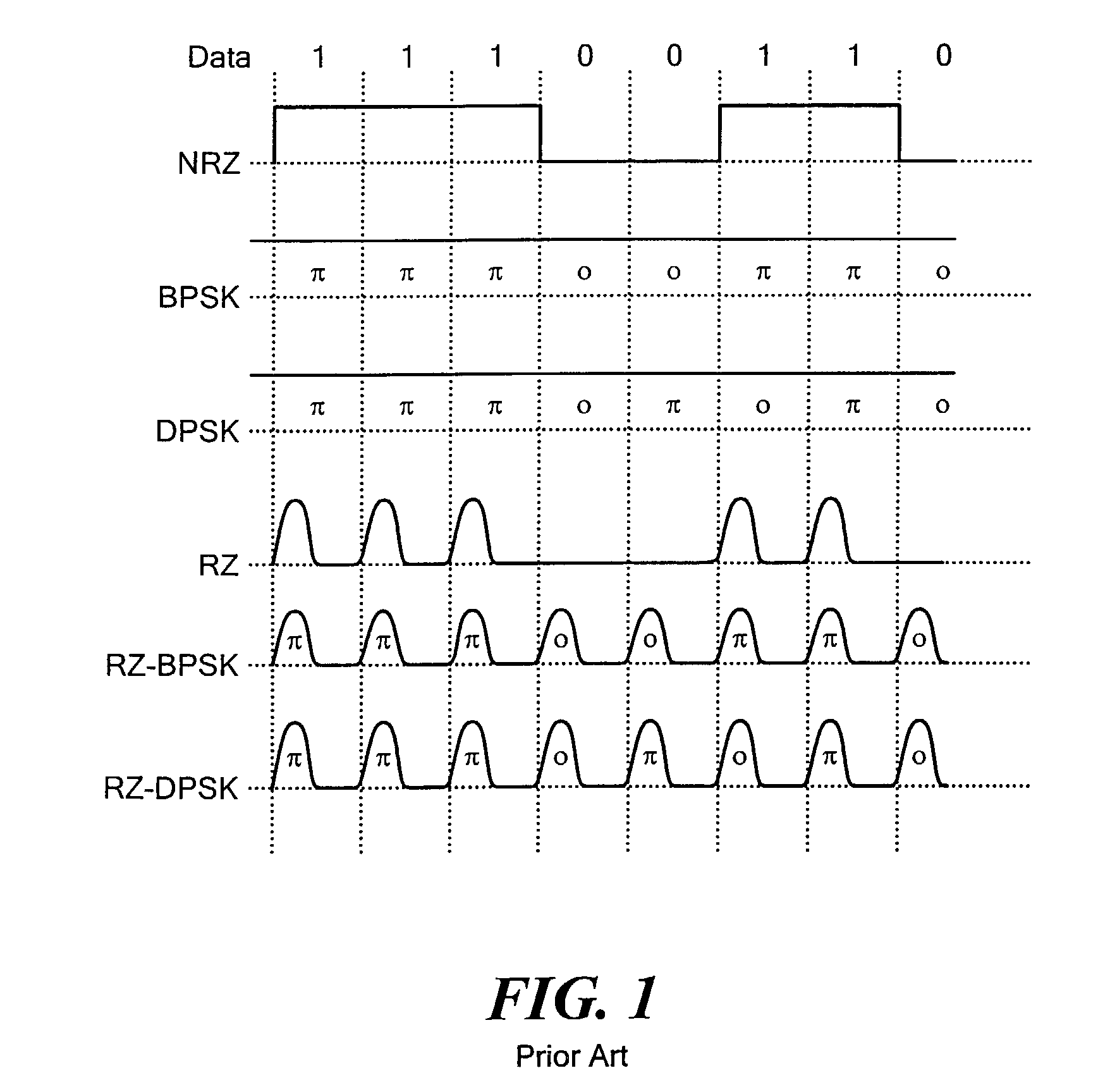
[0025]FIG. 1 illustrates several known optical modulation formats. In non-return-to-zero (NRZ) modulation, each binary digit (1 or 0) is conveyed as a corresponding optical amplitude level (on or off) for the entire bit period. Binary phase-shift key (BPSK) modulation produces a constant-envelope signal in which the binary data modulates the optical phase as 0 or 180 degrees. Differential Phase Shift Key (DPSK) modulation is a variant of BPSK in which the binary data is differentially encoded before optical phase modulation. In return-to-zero (RZ) modulation, one binary digit is represented as a pulse occurring within a bit period, and the other binary digit is represented as no pulse. RZ-BPSK and RZ-DPSK modulation is are forms of BPSK and DPSK respectively in which a return-to-zero amplitude transition is imposed every bit period concurrently with the ...


PUM


Abstract

In an optical transmitter, continuous wave light from a laser passes through a data modulator (DM) for non-return-to-zero (NRZ) encoding of a data stream and through a pulse modulator to add return-to-zero encoding to the modulated optical signal. A modulator controller monitors the output optical signal power, optimizes the bias setting for the DM and the PM, and optimizes the phase relationship between the pulse and data components of the modulated optical signal. For each optimization, a low amplitude and low frequency dither signal is injected at appropriate points in the modulator. A single photo detector and electrical receiver are used in a multiplexed fashion to monitor the optical output signal and derive separate feedback signals. Remaining control circuitry forces a null in a respective residual dither component in the optical output signal to maintain the desired bias level or phase alignment.

Description

CROSS REFERENCE TO RELATED APPLICATIONS[0001]This application claims priority under 35 U.S.C. §119(e) of U.S. Provisional Patent Application No. 60 / 364,822 filed Mar. 15, 2002.STATEMENT REGARDING FEDERALLY SPONSORED RESEARCH OR DEVELOPMENTNot ApplicableBACKGROUND OF THE INVENTION[0002]The present invention relates generally to data encoding and transmission for telecommunications applications, and more specifically to serial encoding to permit reliable and efficient communication of digital data across a fiber optic cable.[0003]In recent years there has been a desire to transmit data across fiber optic cables at ever increasing speed and over longer distances. Current efforts in the industry are targeted at data transmission rates of 40 Gb / s in a single optical channel over hundreds or thousands of kilometers. The demands of such operating frequencies are driving a need for greater performance from system components, such as optical transmitters. Additionally, because of the relativ...

Claims


Application Information

Patent Timeline
IPC IPC(8): H04B10/16H04B10/00H04B10/04G02F1/01H04B10/155H04B10/29
CPCG02F1/0123H04B10/505H04B10/516H04B10/50575H04B10/50577H04B10/5051
Inventor KIMMITT, MYLESKAUFMANN, JOHN E.SHOHET, YUVALSPRINGER, KENTFJELDE, TINAMAMYSHEV, PAVEL V.MIKKELSEN, BENNY P.
Owner LUMENTUM OPTICS INC
Why Eureka
Try Eureka