Temperature sensing device

a temperature sensing and temperature technology, applied in the direction of optical radiation measurement, instruments, heating types, etc., can solve the problems of limited expansion of the sensor into the room or space, inefficient climate control system, and substantial differences between the air temperature measured by the thermostat and the actual ambient air temperature of the space or room. , to achieve the effect of sufficient thermal connection and improved room temperature estimation

Active Publication Date: 2008-07-01
JOHNSON CONTROLS TECH CO
View PDF13 Cites 30 Cited by
  • Summary
  • Abstract
  • Description
  • Claims
  • Application Information

AI Technical Summary

Benefits of technology

[0008]According to another exemplary embodiment a temperature sensing device with housing defining a protrusion is provided. The sensor mounting device coupled to the processor circuit is configured to project one or more sensors into the protrusion in an effort to get an improved estimate of room temperature. The sensor mounting device is simply and securely connected to the processor board while still providing a sufficient thermal connection between the protrusion and the thermal sensor. The flexible circuit permits the processor board to be assembled and disassembled from the enclosure without the inconvenience or danger of damaging or severing the sensor leads.

Problems solved by technology

However, when the thermostat is mounted to the surface of an outside wall or another location where the wall surface is significantly warmer or colder than the air temperature of the space or room, there may be substantial differences between the air temperature measured by the thermostat and the actual ambient air temperature of the space or room.
Under these conditions, the climate control system may perform inefficiently because the temperature measured by the thermostat may not be the ambient air temperature of the room, but rather a temperature somewhere between the air temperature of the room and the wall surface temperature.
In this arrangement extension of the sensor into the room or space is, however, limited by the dimensions of the housing which—in order to provide a low profile appearance—typically affords minimal area.

Method used


Image

  • Temperature sensing device
  • Temperature sensing device
  • Temperature sensing device

Examples


Embodiment Construction

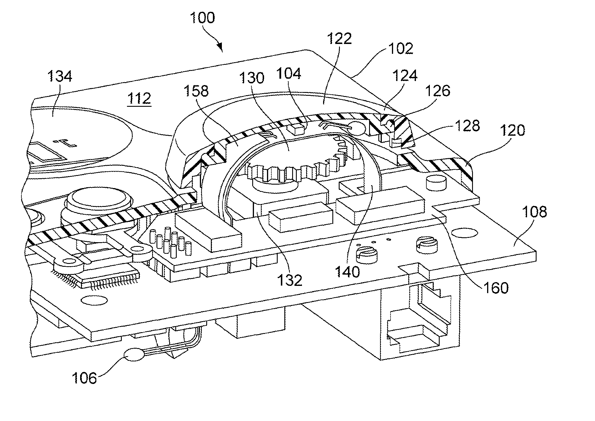
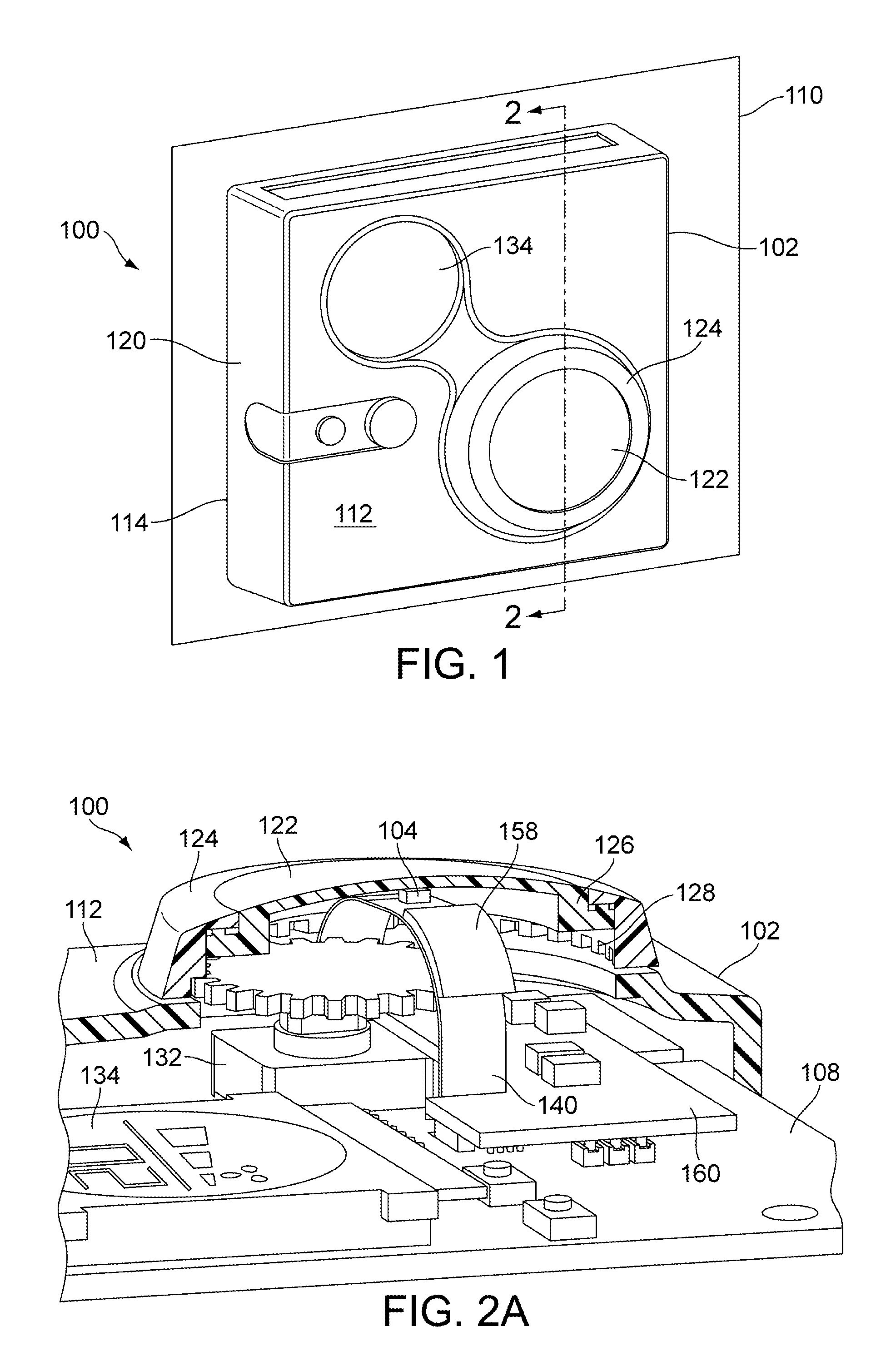
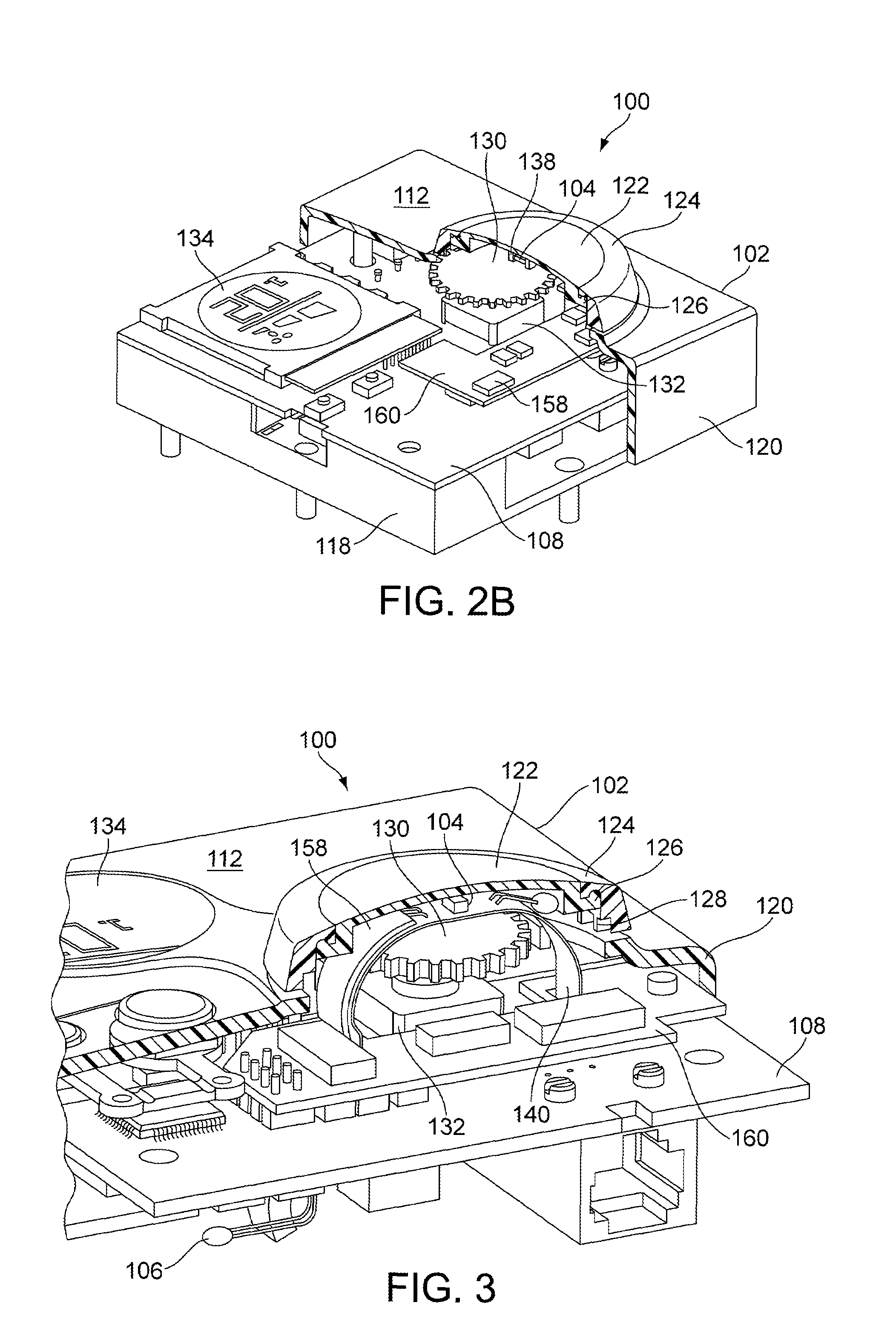
[0017]FIG. 1 illustrates a temperature sensing device 100 according to an exemplary embodiment. Temperature sensing device 100 may be a thermostat, such as a wall-mounted electronic thermostat configured for use with a climate control system to measure the air temperature of a room or space. In other embodiments, temperature sensing device 100 may be adapted for use with other systems or locations. Temperature sensing device 100 includes a housing 102, temperature sensors 104 and 106, mounting device 136, and a processor circuit 108 (as shown in FIGS. 1-7). Temperature sensing device 100 may be generally used to sense a first temperature and a second temperature and to estimate a third temperature using the first temperature and the second temperature. More specifically, temperature sensing device 100 may be used to compensate for external temperature effects resulting from the location of temperature sensing device 100 by measuring a first temperature and a second temperature, and ...


PUM

PropertyMeasurementUnit
temperatureaaaaaaaaaa
temperaturesaaaaaaaaaa
flexibleaaaaaaaaaa

Abstract

The present invention relates to a temperature sensing device with a first temperature sensor mounted to a housing at a first location proximate a first surface of the housing. The first temperature sensor senses a first temperature while a second temperature sensor senses a second temperature. A processor circuit is coupled to the first and second temperature sensors and a mounting device is coupled to either the housing or the processor circuit. The mounting device mounts the second temperature sensor at a second location proximate a second surface of the housing which is spaced apart from the first surface. The processor circuit is configured to estimate a third temperature based on the first and second temperatures and a distance between the first and second locations which is an estimate of a temperature at a third location.

Description

CROSS-REFERENCE TO RELATED PATENT APPLICATIONS[0001]This application is a continuation-in-part of U.S. patent application Ser. No. 10 / 801,313 entitled “Temperature Sensing Device” filed Mar. 16, 2004, the entire contents of which are incorporated herein by reference.BACKGROUND OF THE INVENTION[0002]The present description relates generally to temperature sensing devices such as thermostats, etc. More specifically, the present description relates to mounting devices for sensors in temperature sensing devices.[0003]Climate control systems, such as heating, ventilating, and air conditioning (HVAC) systems, typically include one or more thermostats to monitor, for example, an ambient air temperature within a particular room or space within a building to provide feedback as to whether the air temperature of the room needs to be adjusted to satisfy a predetermined set point. The thermostat is typically configured such that a temperature sensor is housed within an enclosure to sense the te...

Claims


Application Information

Patent Timeline
Patent Type & Authority Patents(United States)
IPC IPC(8): G01K13/00G06F15/00G01K1/20F24F11/00F24F11/02G01K3/00G01K3/14G01K7/00G01K7/42G01K17/04G01K17/20H05B1/02
CPCG01K7/42G01K17/20H05K1/147H05K3/366H05K2201/048H05K2201/10151H05K1/189H05K2201/10598G01K7/427
Inventor KAUTZ, THOMAS O.TICALI, DOMINICFREIMUTH, II, ROBERT R.
Owner JOHNSON CONTROLS TECH CO
Why Eureka
Try Eureka