System and method for signal validation and leakage detection

a signal validation and leakage detection technology, applied in the field of system and method for detecting rf (radio frequency) leakage, can solve problems such as unreliable measurement in that frequency region and noise in that region

Inactive Publication Date: 2008-07-01
COMSONICS
View PDF17 Cites 62 Cited by
  • Summary
  • Abstract
  • Description
  • Claims
  • Application Information

AI Technical Summary

Benefits of technology

[0013]The disadvantages of present signal leakage detectors are substantially overcome with the present invention by providing a novel system and method for signal validation and leakage detection. The present inventive system and method does not encode or inject any test signals into the CATV programming. Accordingly, the subscriber service is not interrupted or degraded in any way. Existing “in use” channels are used to measure the RF carrier signal, which may be leaking from a defective cable or connector. Further, the signal is validated to be sure that the RF receiver is truly receiving RF egress corresponding to the measured RF carrier. Validation permits the user to distinguish between a true RF egress signal and potential noise or electromagnetic interference not related to the CATV plant.
[0014]Off-tuning from the center frequency of a measured RF carrier by a little as 5 or 10 kHz provides reliable data with respect to the signal level. In particular, once off-tuned, a measured RF signal should be lower in amplitude by a significant amount. If the measured signal level of the off-tuned carrier is not reduced by at least 3 dB from the measured level of the carrier frequency, it is presumed that noise exists in that region and measurements in that frequency region are unreliable. Alternate carrier frequencies may be measured, or the leakage testing may be aborted to avoid “false-positive” test results.

Problems solved by technology

If the measured signal level of the off-tuned carrier is not reduced by at least 3 dB from the measured level of the carrier frequency, it is presumed that noise exists in that region and measurements in that frequency region are unreliable.

Method used


Image

  • System and method for signal validation and leakage detection
  • System and method for signal validation and leakage detection
  • System and method for signal validation and leakage detection

Examples


Embodiment Construction

[0030]In this written description, the use of the disjunctive is intended to include the conjunctive. The use of definite or indefinite articles is not intended to indicate cardinality. In particular, a reference to “the” object or thing or “an” object or “a” thing is intended to also describe a plurality of such objects or things.

[0031]It is to be further understood that the title of this section of the specification, namely, “Detailed Description of the Invention” relates to Rules of the U.S. Patent and Trademark Office, and is not intended to, does not imply, nor should be inferred to limit the subject matter disclosed herein or the scope of the invention.

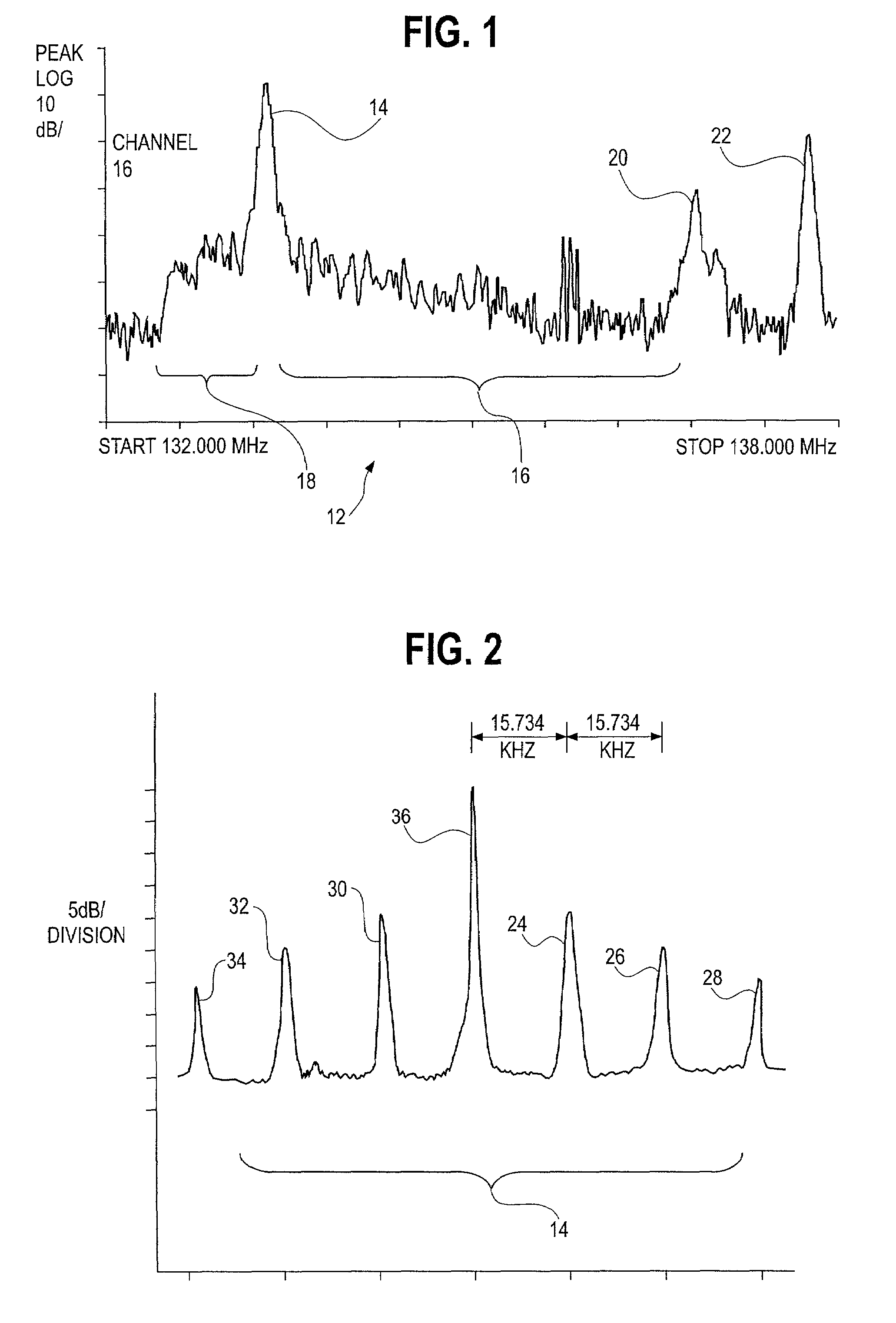
[0032]Referring now to FIG. 1, a typical CATV channel waveform 12 is shown on the screen of a spectrum analyzer, in accordance with NTSC standards. The waveform 12 shows a picture carrier 14, upper side bands 16, lower sidebands 18, a color subcarrier 20 and a sound carrier 22. In the illustrated embodiment, the waveform 12 corr...


PUM


Abstract

A system and method of validating signals and detecting signal leakage in a cable communications includes the steps of a) tuning a radio frequency receiver to a carrier frequency of a selected RF channel, b) measuring a signal level of the carrier frequency, c) off-tuning the receiver by a predetermined offset, d) measuring a signal level of the off-tuned carrier frequency, e) obtaining a signal level difference between the signal level of the carrier frequency and the signal level of the off-tuned carrier frequency to determine if interference exists, f) declaring an interference condition if the signal level difference is less than a predetermined difference amount, and g) providing an indication of the signal level of the carrier frequency to permit a determination of whether a signal leakage condition exists.

Description

BACKGROUND OF THE INVENTIONFIELD OF THE INVENTION[0001]The present invention relates generally to a system and method for detecting RF (Radio Frequency) leakage in a cable television or CATV system, and more specifically to a system and method for signal validation and leakage detection (RF egress) using an existing RF channel without disruption of the channel subscriber service or channel programming.[0002]Cable television is a system for delivering television signals to subscribers or viewers by means of coaxial cable. Additionally, fiber optic cable and microwave links may be used. For a monthly fee, cable television viewers receive a clear picture of local channels, as well as reception of many additional channels, including many channels devoted to movies, sports, news or special events. Originating in 1949 as a way of providing good signal reception to geographic areas where the conventional television signals were weak, cable spread quickly among rural municipalities, and can...

Claims


Application Information

Patent Timeline
Patent Type & Authority Patents(United States)
IPC IPC(8): H04N7/173H04B17/00H04B1/00H04L1/24H04N17/00
CPCH04B17/0085H04L1/24H04N7/17309H04B17/23H04B17/309H04N17/00H04B17/354H04B17/345
Inventor RUNZO, JOSEPH DONALD
Owner COMSONICS
Why Eureka
Try Eureka