Formation testing apparatus and method for smooth draw down

a technology of formation testing and smooth draw down, which is applied in the direction of earthwork drilling, well accessories, borehole/well accessories, etc., can solve the problems of affecting the formation, affecting the formation, and affecting the formation,

Inactive Publication Date: 2008-07-08
BAKER HUGHES INC
View PDF21 Cites 25 Cited by
  • Summary
  • Abstract
  • Description
  • Claims
  • Application Information

AI Technical Summary

Benefits of technology

[0026]In yet another aspect of the present invention is a system for determining in situ a desired formation parameter of interest. The system includes a work string for conveying a tool into a well borehole traversing a formation and a test unit in the tool, the test unit being adapted for fluid communication with the formation, the test unit including a test volume for receiving fluid from the formation. A control device is associated with the test volume for controlling pressure in the test volume dec...

Problems solved by technology

Although wireline conveyed tools are capable of testing a reservoir, it is difficult to convey a wireline tool in a deviated borehole.
A drawback of this type of tool is encountered when different formations are penetrated during drilling.
If formation pressure is lower than expected, the pressure from the mud column may cause unnecessary damage to the formation.
If the formation pressure is higher than expected, a pressure kick could result.
Such formation pressure testing can be hampered by a variety of factors including insufficient draw down volume, tool or formation plugging during a test, seal failure, or pressure supercharging.
These factors can result in false pressure information.
The excessive draw rate often results in an excessive delta pressure drop between the test volume and the formation causing long build up times. Moreover, compressibility of fluid in the tool will dominate the pressure response if the formation cannot provide enough fluid for the excessive pressure drop.
With an excessive draw rate the pressure drop can exceed the fluid bubble point thereby causing gas to evolve from the fluid and corrupt the test result.
The multiple draw test using the same test parameters suffers from inefficiency of time and the possibility of repeating erroneous results.
Merely following a predetermined test protocol does not increase efficiency, because the protocol might not address real-time conditions in a timely manner.
Furthermore, predetermine...

Method used


Image

  • Formation testing apparatus and method for smooth draw down
  • Formation testing apparatus and method for smooth draw down
  • Formation testing apparatus and method for smooth draw down

Examples


Embodiment Construction

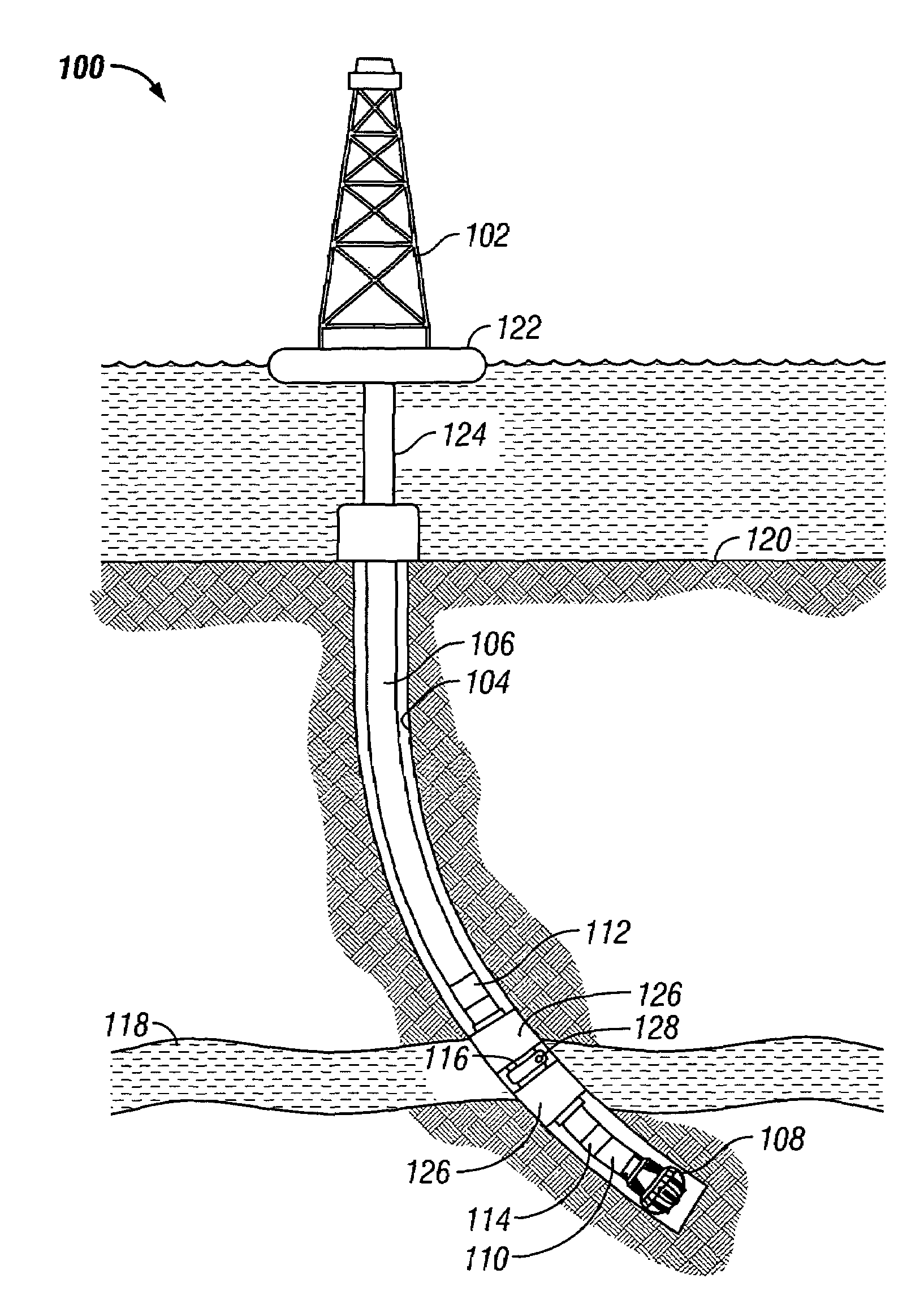
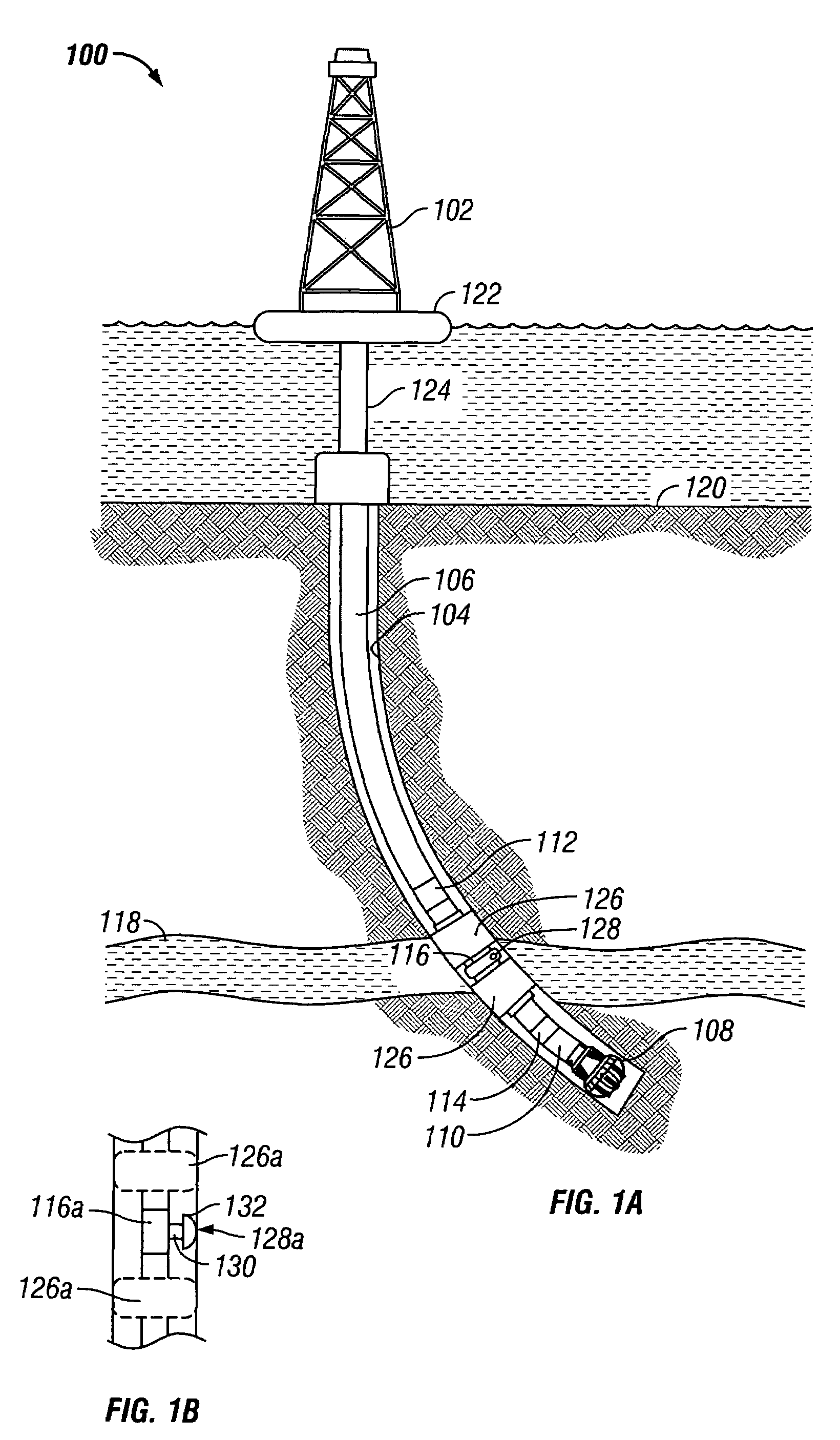
[0040]FIG. 1A is a drilling apparatus 100 according to one embodiment of the present invention. A typical drilling rig 102 with a borehole 104 extending therefrom is illustrated, as is well understood by those of ordinary skill in the art. The drilling rig 102 has a work string 106, which in the embodiment shown is a drill string. The drill string 106 has attached thereto a drill bit 108 for drilling the borehole 104. The present invention is also useful in other types of work strings, and it is useful with a wireline, jointed tubing, coiled tubing, or other small diameter work string such as snubbing pipe. The drilling rig 102 is shown positioned on a drilling ship 122 with a riser 124 extending from the drilling ship 122 to the sea floor 120. However, any drilling rig configuration such as a land-based rig or a wireline may be adapted to implement the present invention.

[0041]If applicable, the drill string 106 can have a down hole drill motor 110. Incorporated in the drill string ...


PUM


Abstract

A method and apparatus for of determining a formation parameter of interest. The method includes placing a tool into communication with the formation to test the formation and drawing down a test volume at an increasing draw rate during a first draw period and decreasing the draw rate during a second draw period to create a smooth draw down cycle. The draw down can be step-wise or continuous. The formation parameter is determined using formation rate analyis and characteristics determined during the draw down cycle.

Description

CROSS REFERENCE TO RELATED APPLICATIONS[0001]The present application is a continuation-in-part of U.S. patent application Ser. No. 10 / 423,420 for “Formation Testing Apparatus and Method for Optimizing Draw Down” filed on Apr. 25, 2003 now U.S. Pat. No. 7,011,155, which is a continuation-in-part of U.S. patent application Ser. No. 09 / 910,624 for “Procedure for Fast and Extensive Formation Evaluation with Minimum System Volume” filed on Jul. 20, 2001 now U.S. Pat. No. 6,568,487 and is further a continuation-in-part of U.S. patent application Ser. No. 09 / 910,209 for “Closed-Loop Drawdown Apparatus and Method for In-situ Analysis of Formation Fluids” filed on Jul. 20, 2001 now U.S. Pat. No. 6,609,568. The specification of each above-identified application is incorporated herein by reference.BACKGROUND OF THE INVENTION[0002]1. Field of the Invention[0003]This invention generally relates to the testing of underground formations or reservoirs. More particularly, this invention relates to a...

Claims


Application Information

Patent Timeline
IPC IPC(8): E21B49/10E21B49/00E21B49/08
CPCE21B49/087E21B49/008E21B49/08E21B49/10
Inventor NIEMEYER, EICKKISCHKAT, TOBIASMEISTER, MATTHIAS
Owner BAKER HUGHES INC
Why Eureka
Try Eureka