
Brine container with filter system

a filter system and container technology, applied in the field of brine containers, can solve the problems of gradual contamination of the brine filter

Inactive Publication Date: 2008-07-08
SCHRDER MASCHBAUU KG
View PDF19 Cites 1 Cited by
  • Summary
  • Abstract
  • Description
  • Claims
  • Application Information

AI Technical Summary

Benefits of technology

[0004]It is an object of the invention to provide a brine container of the type named above, for which the suction filter can be unburdened permanently and reliably.
[0006]Accordingly, the brine can be pumped constantly through the circulating filter system and, at the same time, be filtered. In this way, impurities are removed from the brine. Due to the circulating filter system, dirt particles can be removed effectively and to a large extent from the circulating brine, so that the suction filter is relieved and is contaminated only much slower. Furthermore, during an exchange of filter elements, brine can continue to be removed from the brine container over the suction filter, so that a pickling machine, for example, can be operated continuously. This is particularly advantageous, since the filter element can be exchanged or removed and cleaned without interrupting the production.
[0008]In a preferred embodiment, the brine container has a recycling region and a separate suction region. The suction filter is disposed in the suction region and the brine can be pumped by the pump of the circulating filter system from the recycling region into the suction region. In this connection, it is a particular advantage that the suction region is supplied with brine, which was filtered by the filter system. As a result, the degree of contamination is less in the suction region of the brine container than in the recycling region of the brine container. Because of the lesser degree of contamination, there is a clearly lesser burden on the suction filter, which becomes contaminated, if the worst comes to the worst, very slowly. For exchanging the filter element, the inlet to the filter preferably can be shut off, so that the filter or the filter element can be removed without pumping unfiltered brine into the suction region. Alternatively, the pump could also be switched off for exchanging the filter element. In both cases, it is advantageous that, when a filter element is exchanged, unfiltered brine cannot reach the suction region. In continuous operation, the suction filter can this be unburdened even more effectively.
[0009]In a preferred embodiment, the recycling region and the suction region are connected by a permeable separation filter. The separation filter is made, for example, from sheet metal with slots or other openings. The separation filter permits transfer of brine between the recycling region and the suction region of the brine container and enables the levels in the two regions to equalize. Since, depending on the output of the pump of the filter system, hardly any brine flows through the separation filter or the brine flows essentially from the suction region back into the recycling region, the separation filter is hardly contaminated. Some flow in the brine container, caused by the pump of the filter system, is advantageous in order to keep the brine in motion, so that fewer solids are deposited at the bottom.
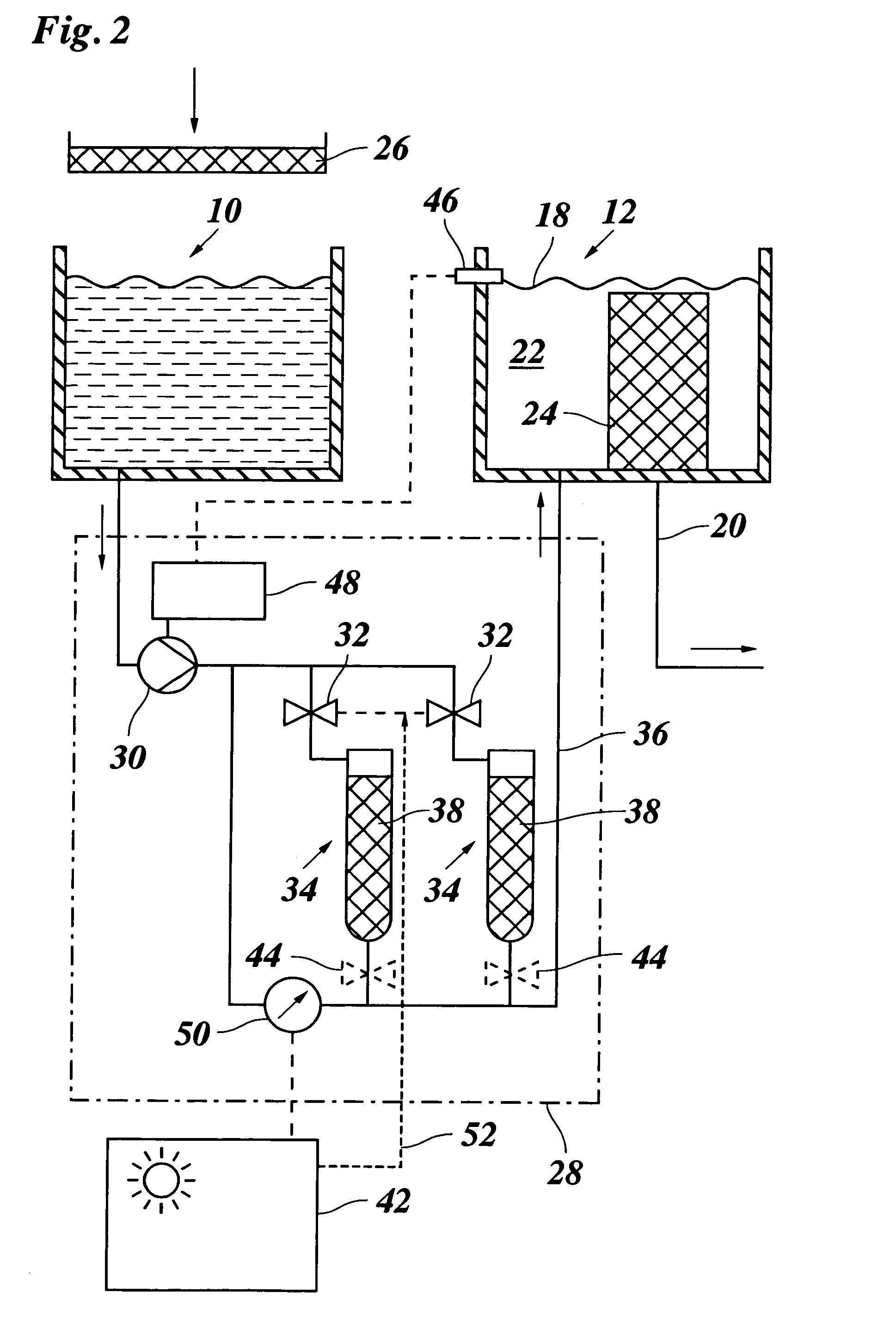
[0012]Preferably, the filter system has a pressure-measuring device for measuring the pressure difference in front of and behind the filter. This may be connected, for example, to a monitoring device for the pressure difference, which emits a signal when a limiting value is exceeded. If, for example, the difference in pressure becomes too large because of contamination of the filter, then this can be indicated on a display, which points out the need to change the filter, so that there is no need to check the filter visually.
[0013]In the case of several filters, which can be switched by the switching device, switching from an active filter to another filter can also be automatic when a limiting value of the pressure difference is exceeded. In this way, when a filter is full, it is possible to switch automatically to the next filter, so that the latter is used and the full filter can meanwhile be exchanged.

Problems solved by technology

The slide filter becomes contaminated gradually and must be removed at regular intervals for cleaning purposes.

Method used


Image

  • Brine container with filter system
  • Brine container with filter system
  • Brine container with filter system

Examples


Embodiment Construction

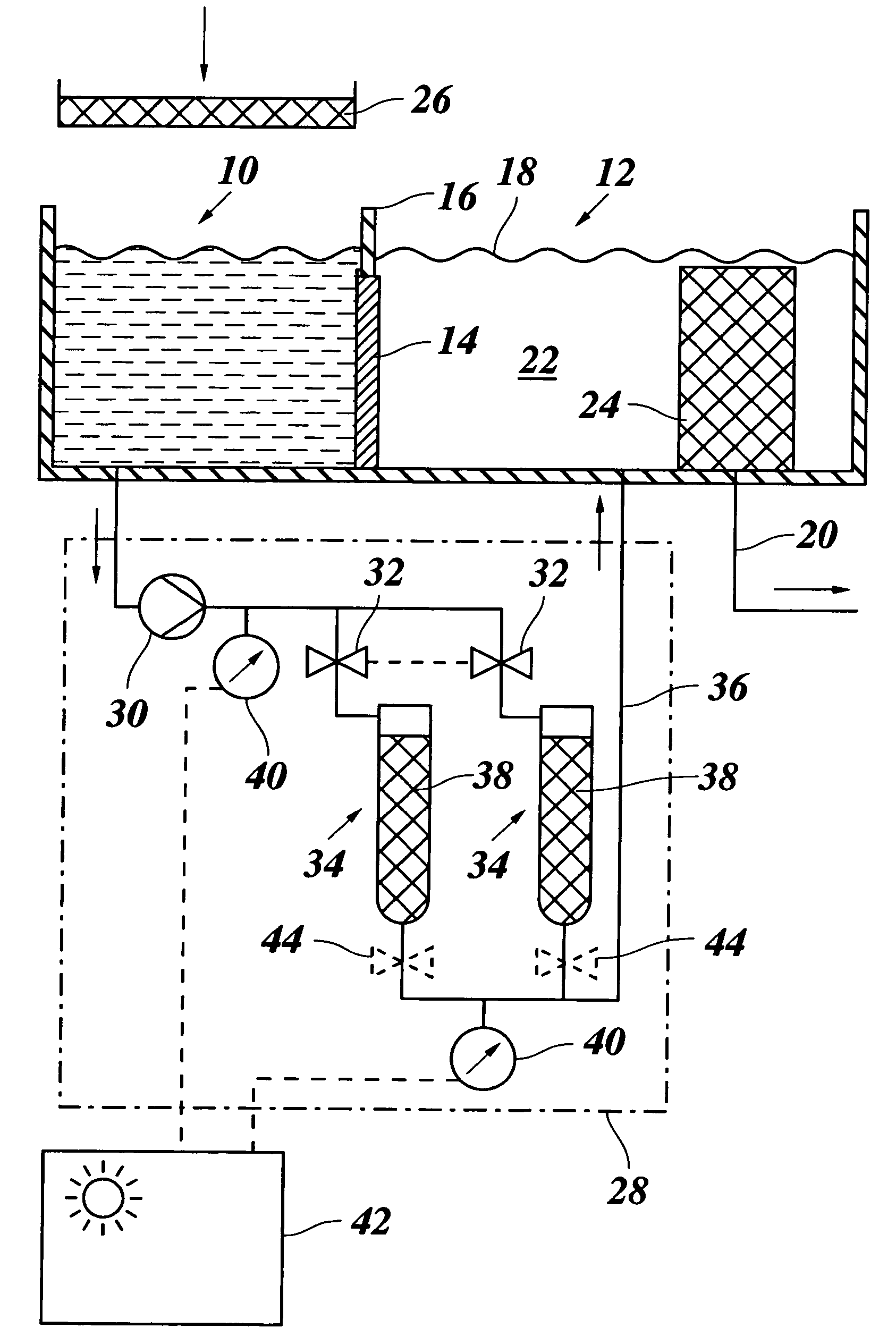
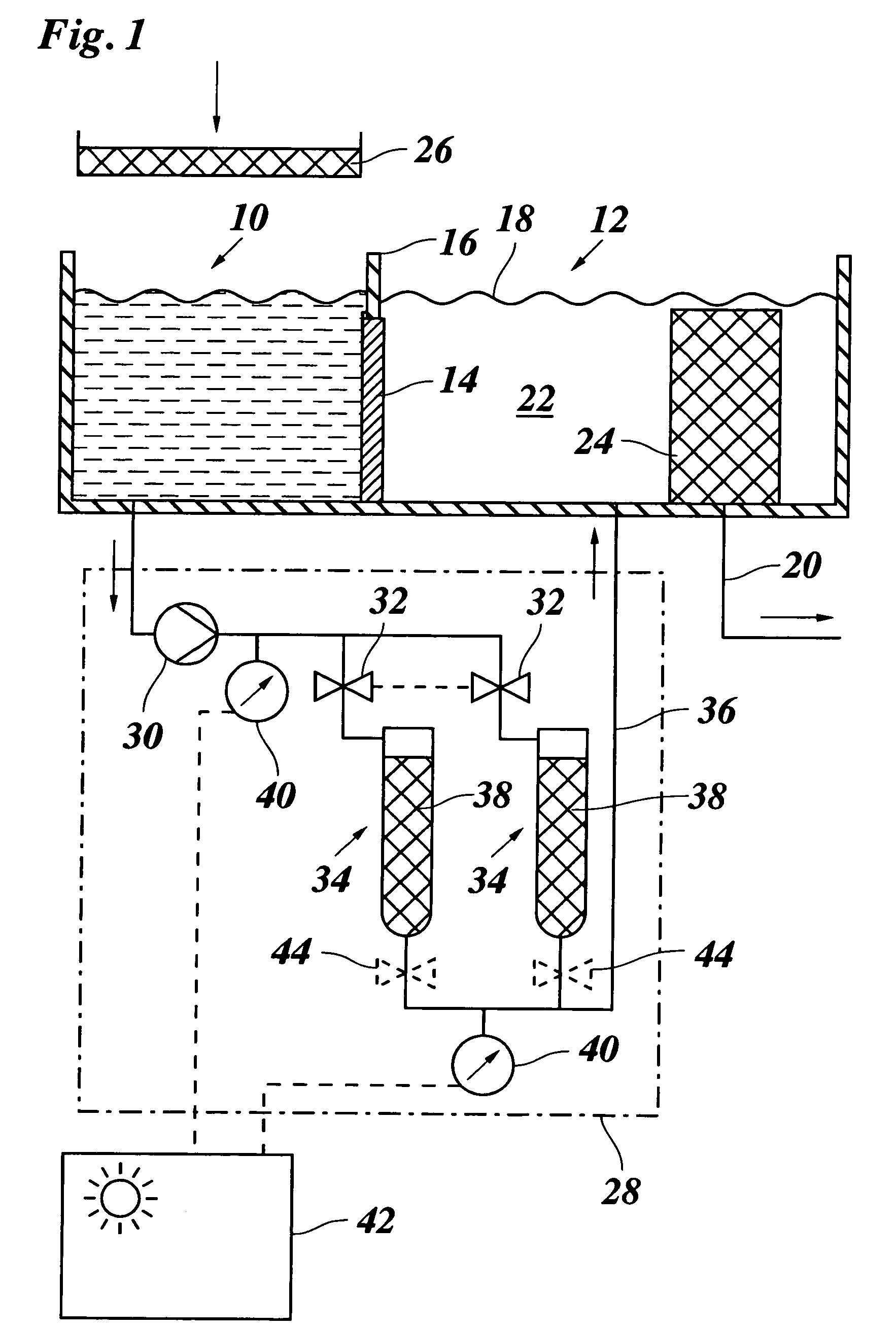
[0018]FIG. 1 shows a brine container with a recycling region 10 and a suction region 12, which are separated from one another by a separating filter 14, which is inserted in the brine container. The separation filter 14, in its upper region, has a wall 16, with which it protrudes above the liquid surface 18. The brine container is, for example, part of a pickling machine, which is supplied with pickling brine 22, which is aspirated through a suction filter 24, by means of a pump over a suction pipeline 20. The suction filter 24 produces, for example, a finer filtration than does the separation filter 14.

[0019]Brine, discharging from the pickling machine, is recycled over a coarse filter 26 to the recycling region 10. After the coarse filtration, the brine in the recycling region 10 still has a certain degree of contamination. The recycling region 10 and the suction region 12 are connected by a circulating filter system 28, which is shown symbolically and explained in greater detail ...


PUM

PropertyMeasurementUnit
permeableaaaaaaaaaa
pressureaaaaaaaaaa
timeaaaaaaaaaa

Abstract

Brine container, at which a suction filter (24) is disposed, in which the brine container has a circulating filter system (28), which has a filter (34) and a pump (30), with which the brine (22) can be pumped through the circulating filter system (28), the filter (34) having an exchangeable filter element (38).

Description

BACKGROUND OF THE INVENTION[0001]The invention relates to a brine container, at which a suction filter is disposed.[0002]It may, for example, be a brine container for pickling brine, which is pumped away through the suction filter and supplied to a pickling machine. Usually, pickling brine, flowing off from the pickling machine, is recycled over a coarse filter into the brine container. The function of the suction filter is to protect the brine pump and to prevent blockage of the injection needles of the pickling machine by particles or impurities that have been introduced. Over time, the suction filter is blocked by particles filtered out of the pickling brine and can be removed manually, for example, for cleaning purposes.[0003]It is known that an additional filter may be provided between the coarse filter and the suction filter in the brine container in order to avoid rapid blockage of the suction filter. Usually, a slide filter is pushed for this purpose from above into the brin...

Claims


Application Information

Patent Timeline
Patent Type & Authority Patents(United States)
IPC IPC(8): A23B4/26A01J25/00A23B4/02A23B4/28E21B21/06
CPCA23B4/02A23B4/285A23B4/28A23B4/26Y02A40/90
Inventor HEIDBREDER, ERICUMBACH, CHRISTOPH
Owner SCHRDER MASCHBAUU KG
Learn More