
Energy harvesting using a thermoelectric material

a thermoelectric material and energy harvesting technology, applied in the direction of thermoelectric device junction materials, piezoelectric/electrostrictive/magnetostrictive devices, thermoelectric devices, etc., can solve the problem of too low practical application requirements, and achieve the effect of reducing power requirements

Inactive Publication Date: 2008-07-08
LAWRENCE LIVERMORE NAT SECURITY LLC
View PDF14 Cites 41 Cited by
  • Summary
  • Abstract
  • Description
  • Claims
  • Application Information

AI Technical Summary

Benefits of technology

The system achieves a significantly higher Seebeck coefficient, several orders of magnitude larger than current state-of-the-art materials, allowing for efficient energy harvesting from various sources, including hot engines, computers, and environmental temperature cycles, reducing power requirements and enabling the powering of devices.

Problems solved by technology

However, current state of the art thermoelectric materials utilized to harvest waste heat and convert such heat to a useful energy, for example, devices that use a combination of n-type and p-type materials, generally have Seebeck coefficients on the order of several 100 μV°K−1, which is too low for practical applications.

Method used


Image

  • Energy harvesting using a thermoelectric material
  • Energy harvesting using a thermoelectric material
  • Energy harvesting using a thermoelectric material

Examples


Embodiment Construction

[0019]Referring now to the following detailed information, and to incorporated materials; a detailed description of the invention, including specific embodiments, is presented.

[0020]Unless otherwise indicated, numbers expressing quantities of ingredients, constituents, reaction conditions and so forth used in the specification and claims are to be understood as being modified by the term “about.” Accordingly, unless indicated to the contrary, the numerical parameters set forth in the specification and attached claims are approximations that may vary depending upon the desired properties sought to be obtained by the subject matter presented herein. At the very least, and not as an attempt to limit the application of the doctrine of equivalents to the scope of the claims, each numerical parameter should at least be construed in light of the number of reported significant digits and by applying ordinary rounding techniques. Notwithstanding that the numerical ranges and parameters setti...


PUM

PropertyMeasurementUnit
temperatureaaaaaaaaaa
frequencyaaaaaaaaaa
frequenciesaaaaaaaaaa

Abstract

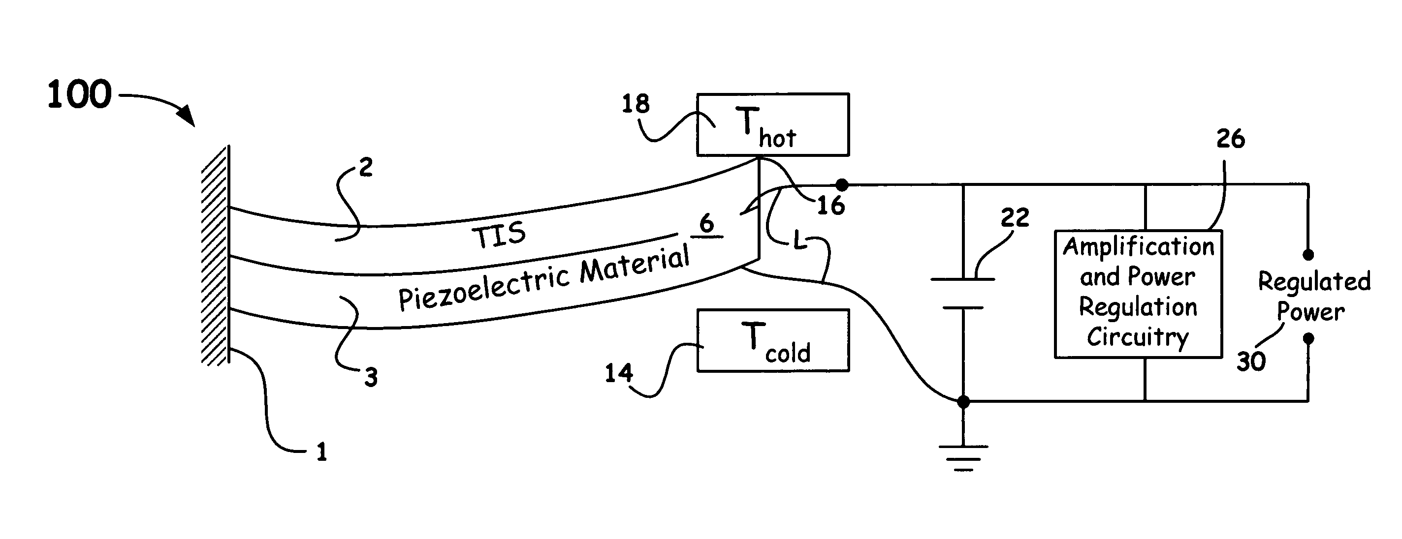
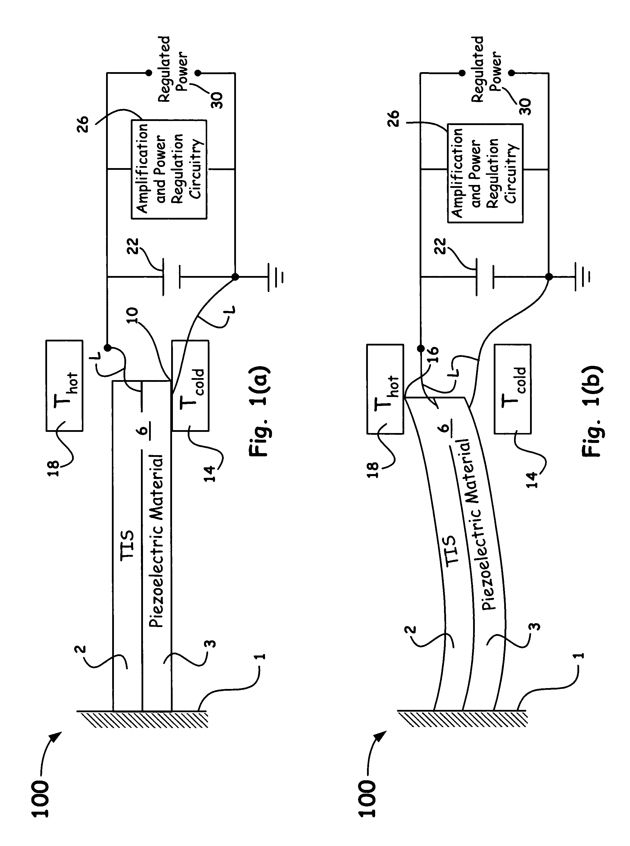
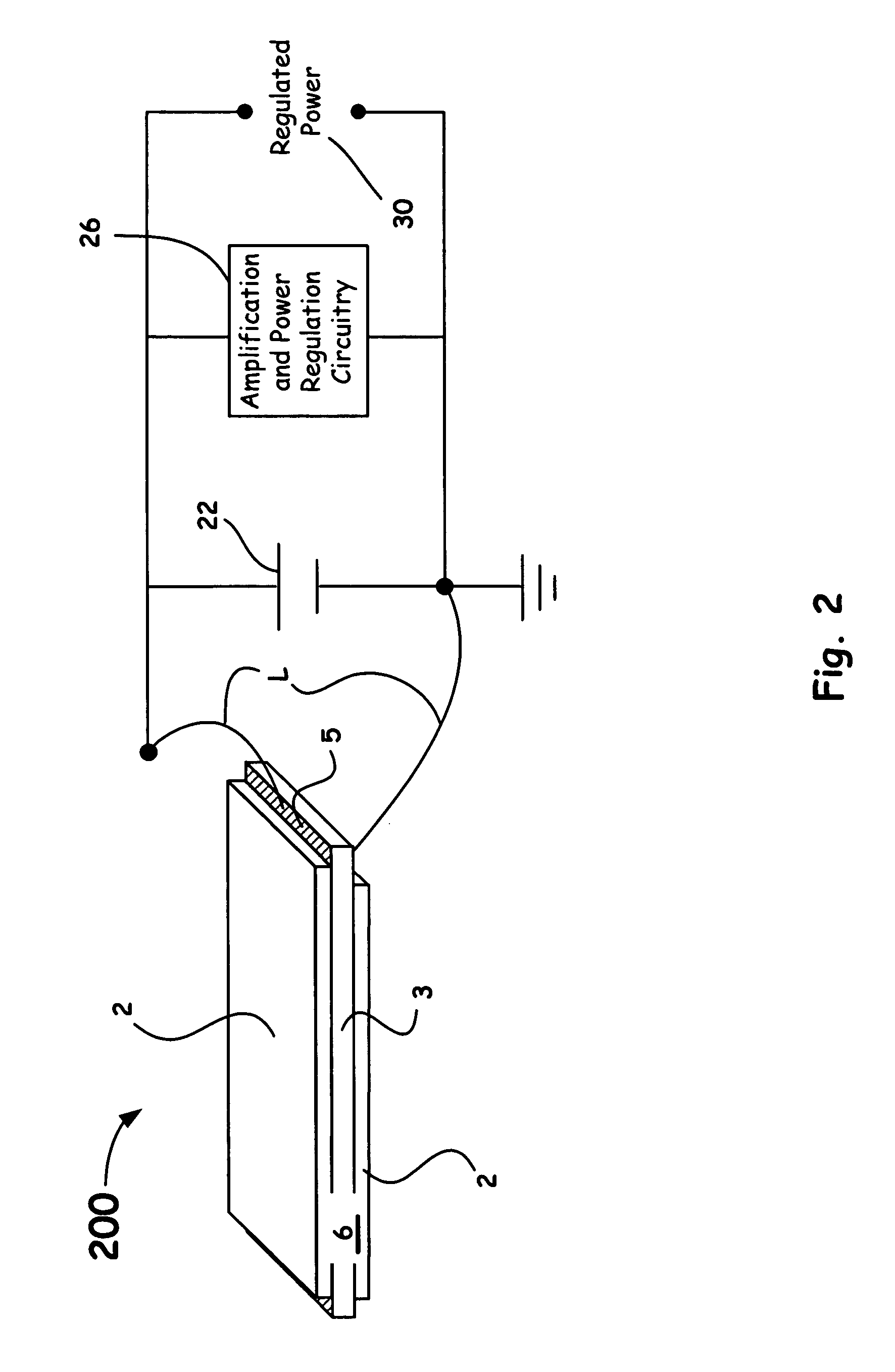
A novel energy harvesting system and method utilizing a thermoelectric having a material exhibiting a large thermally induced strain (TIS) due to a phase transformation and a material exhibiting a stress induced electric field is introduced. A material that exhibits such a phase transformation exhibits a large increase in the coefficient of thermal expansion over an incremental temperature range (typically several degrees Kelvin). When such a material is arranged in a geometric configuration, such as, for a example, a laminate with a material that exhibits a stress induced electric field (e.g. a piezoelectric material) the thermally induced strain is converted to an electric field.

Description

CROSS-REFERENCE TO RELATED APPLICATIONS[0001]This application claims the benefit of U.S. Provisional Application No. 60 / 554,747, filed Mar. 19, 2004, entitled “Energy Harvesting System Using A Thermoelectric Material,” which is incorporated herein by this reference.[0002]The United States Government has rights in this invention pursuant to Contract No. W-7405-ENG-48 between the United States Department of Energy and the University of California for the operation of Lawrence Livermore National Laboratory.BACKGROUND OF THE INVENTION[0003]1. Field of the Invention[0004]The present invention relates in general to an energy harvesting system / method and, more particularly, to a method / system that includes a thermostrictive material and a piezoelectric element, such as, a laminate capable of harvesting waste heat.[0005]2. Description of Related Art[0006]Waste heat is always generated whenever work is done. Harvesting such waste heat can increase the efficiency of engines, be used to power ...

Claims


Application Information

Patent Timeline
Patent Type & Authority Patents(United States)
IPC IPC(8): H01L41/08H10N10/13H10N30/00H10N10/85H10N30/30
CPCH02N2/18H01L41/1136H10N30/306
Inventor NERSESSIAN, NERSESSECARMAN, GREGORY P.RADOUSKY, HARRY B.
Owner LAWRENCE LIVERMORE NAT SECURITY LLC
Learn More