
Control and/or monitoring apparatus and method

Inactive Publication Date: 2008-07-08
JOAO CONTROL & MONITORING SYST LLC
View PDF440 Cites 267 Cited by
  • Summary
  • Abstract
  • Description
  • Claims
  • Application Information

AI Technical Summary

Benefits of technology

[0039]The command code data is then transmitted to, or read by, the CPU for command code identification and for further processing, if necessary. In this manner, an authorized user or operator, upon learning of the theft of the vehicle, or simply attempting to ascertain the status and / or location of the vehicle, may easily access and / or activate the apparatus by simply “calling up” or transmitting a signal to the apparatus.
[0134]It is another object of the present invention to provide a control, monitoring and / or security apparatus and method which facilitates the control of the movement, the motion or the operation of any of the vehicles and / or premises and / or any of the systems, devices and / or components of and / or associated with the respective vehicles and / or premises.

Problems solved by technology

However, as is well known, these known anti-theft and / or vehicle recovery devices or systems may be easily defeated by thieves, and especially, by professional thieves and / or have other disadvantages associated with their use.
Experience has shown that even the most sophisticated of anti-theft devices may be defeated by an experienced, and determined, thief, and that vehicle recovery systems also have drawbacks associated with their use.
In the case of some vehicle recovery devices, their use may be limited by the availability, or lack thereof, of the corresponding tracker or receiver device(s) in the particular locality, or the lack of same by the law enforcement department in a particular area.
In recent times, an even more disturbing criminal practice, involving the theft of motor vehicles, has rendered most anti-theft devices virtually useless.
However, once surrendered, the motor vehicle is virtually lost to the car thief.
Anti-theft and / or theft-deterrent devices which attempt to defeat the ultimate vehicle theft, such as caused by car-jacking, by disabling the motor vehicle during the “getaway”, such as by shutting off power to the motor vehicle engine, have major disadvantages and drawbacks in that they could shut-off the vehicle engine at an inopportune instant in time, thereby causing a dangerous condition to exist which could lead to an accident and resulting injuries to individuals as well as damage to property.
These accidents may arise when the motor vehicle power is suddenly shut-off while the vehicle is in motion, which condition could cause the vehicle to suddenly, or even gradually, lose power on a roadway or highway, while traveling at a moderate or at a high rate of speed and / or when a power steering and / or a power braking system, which derives its power from the vehicle engine, suddenly loses power upon the loss of the engine power.
As noted above, accidents such as these may result in injuries to people, both inside and outside the vehicle, as well as property damage caused by, and to, the vehicle.
The above described disadvantages and drawbacks of the prior art devices may also pose accident liability concerns to those manufacturers and / or sellers of these devices, as well as to the owner or operator of the motor vehicle, as these entities and / or individuals may be held liable for the injuries and / or the damages sustained as a result of the above described accidents.
Unless the local police or law enforcement authorities have such equipment, the homing signal recovery device serves little purpose in recovering the vehicle in that locale.
Other vehicle recovery systems require that a police report be made prior to an activation of the homing and / or recovery equipment, which practice could result in the loss of valuable time in the vehicle recovery process.
The above problems concerning vehicle security are equally applicable to and present an equal or even greater problem in providing security for marine vessels and vehicles, aircraft and / or recreational vehicles.
While anti-theft and / or security systems exist for residential and / or commercial premises, such systems fail to enable the owner or occupant and / or other authorized individual to conveniently and effectively exercise and / or perform control, monitoring and / or security functions with regards to these premises.

Method used


Image

  • Control and/or monitoring apparatus and method
  • Control and/or monitoring apparatus and method
  • Control and/or monitoring apparatus and method

Examples


Embodiment Construction

taken in conjunction with the Drawings which follow.

BRIEF DESCRIPTION OF THE DRAWINGS

In the Drawings:

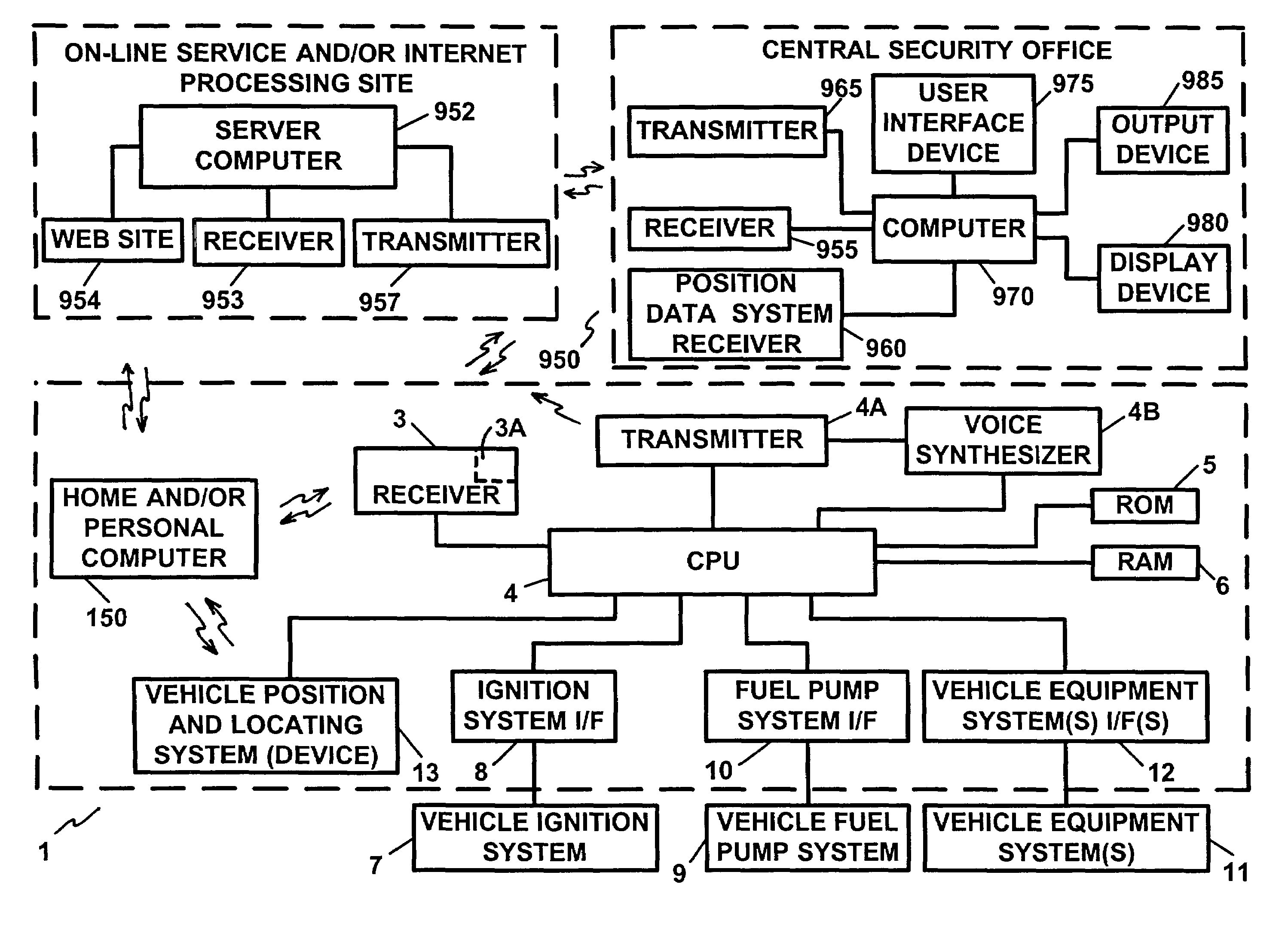
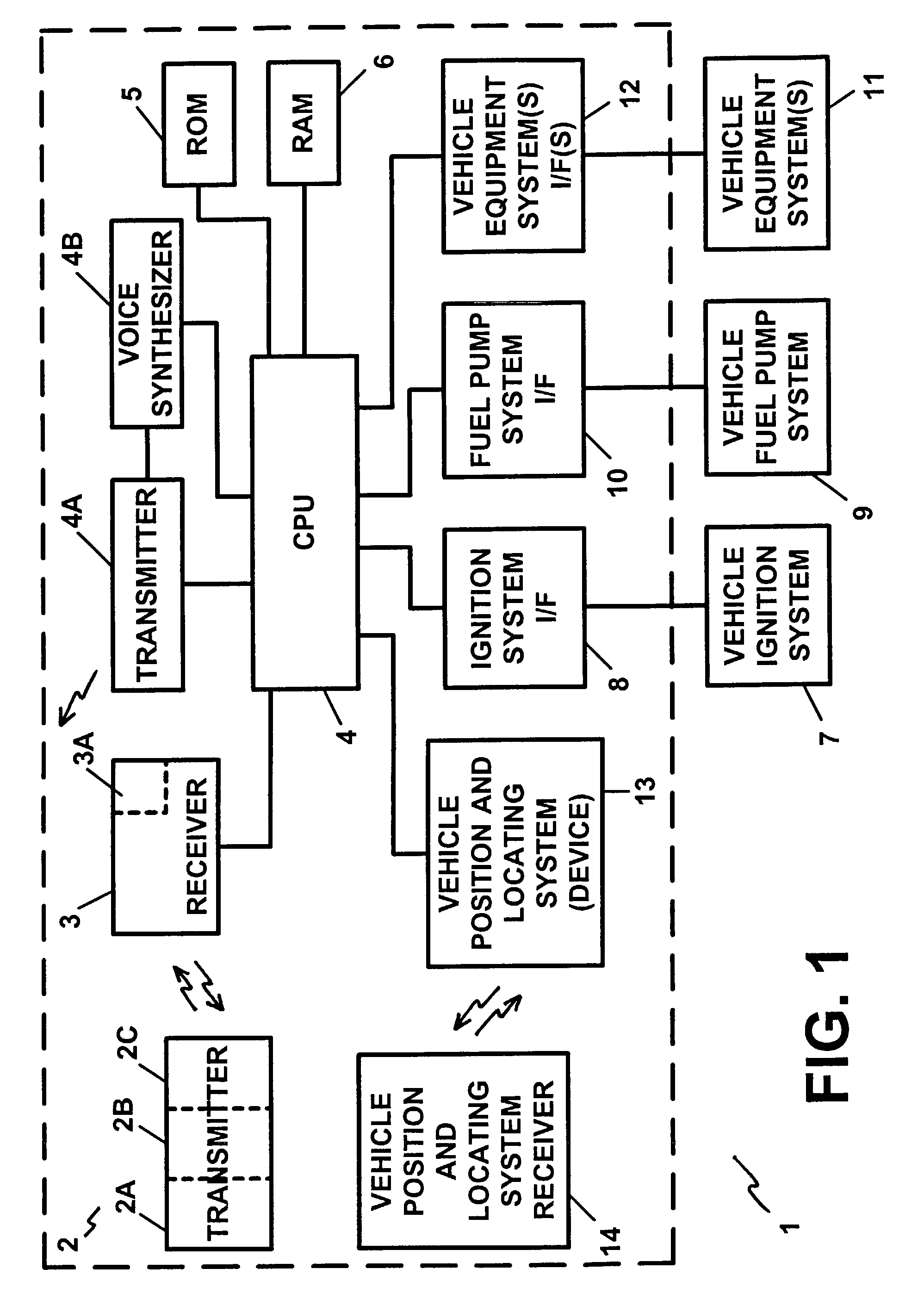
[0141]FIG. 1 illustrates a block diagram of the apparatus which is the subject of the present invention;

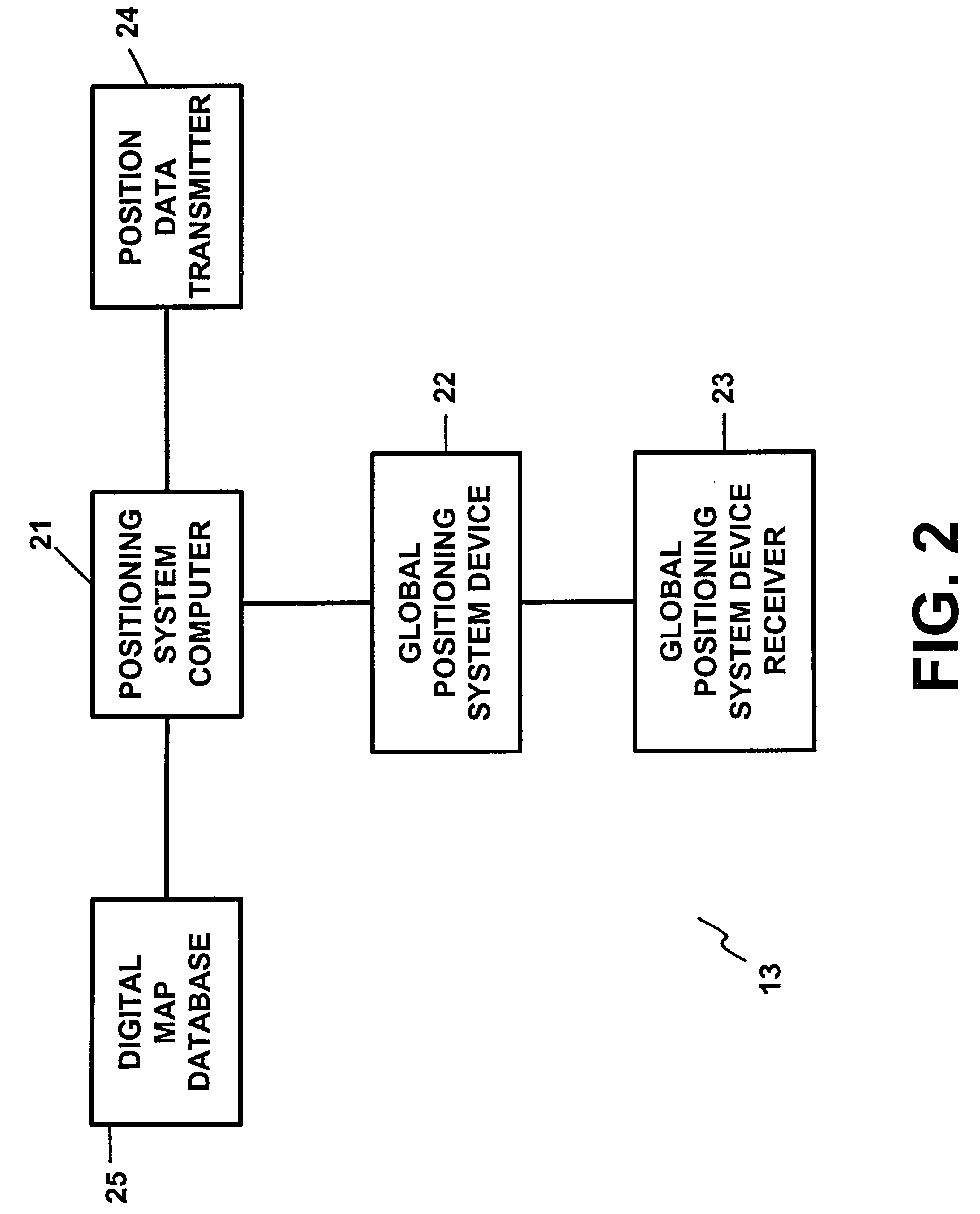
[0142]FIG. 2 illustrates the vehicle position and locating device of FIG. 1 illustrating the main components thereof in block diagram form;

[0143]FIG. 3 illustrates the vehicle position and locating system receiver of FIG. 1 illustrating the components thereof in block diagram form;

[0144]FIG. 4 illustrates a block diagram of a computer system which is utilized in another preferred embodiment of FIG. 1 for performing the functions of, and for, the transmitter and the vehicle position and locating system receiver of the apparatus of the present invention;

[0145]FIG. 5A illustrates the apparatus of FIG. 1 wherein the computer of FIG. 4 is utilized in another preferred embodiment in order to replace and to perform the functions of the transmitter and the vehicle position and locating sys...


PUM


Abstract

An apparatus including a first device which generates and / or transmits a first signal and which is associated with a web site and located remote from a premises or vehicle. The first signal is transmitted in response to a second signal transmitted from a second device located remote from the first device and remote from the premises or vehicle. The first device determines whether an action or an operation associated with the second signal is authorized or allowed and, if so, transmits the first signal to a third device located at the premises. The second signal is transmitted via the Internet and / or the World Wide Web. The third device generates and / or transmits a third signal for activating, de-activating, disabling, re-enabling, and / or controlling an operation of, a system, device, equipment, equipment system, component, and appliance, of the premises or vehicle.

Description

RELATED APPLICATIONS[0001]This application is a continuation-in-part application of U.S. patent application Ser. No. 09 / 551,365, filed Apr. 17, 2000, now U.S. Pat. No. 6,542,076, which is a continuation-in-part application of U.S. patent application Ser. No. 09 / 277,935, filed Mar. 29, 1999, now U.S. Pat. No. 6,549,130, which is a continuation application of U.S. patent application Ser. No. 08 / 683,828, filed Jul. 18, 1996, now U.S. Pat. No. 5,917,405, which is a continuation-in-part application of U.S. patent applicatian Ser. No. 08 / 622,749, filed Mar. 27, 1996, abandoned. U.S. patent application Ser. No. 09 / 551,365, filed Apr. 17, 2000, now U.S. Pat. No. 6,542,076, also claims the benefit of priority of U.S. Provisional Patent Application Ser. No. 60 / 187,735, filed Mar. 8, 2000, and U.S. Provisional Patent Application Ser. No. 60 / 190,379, filed Mar. 17, 2000.FIELD OF THE INVENTION[0002]The present invention pertains to a control, monitoring and / or security apparatus and method and, ...

Claims


Application Information

Patent Timeline
IPC IPC(8): G08B1/08B60R25/10
CPCB60R25/102B60R25/252B60R25/33B60R25/018B60R25/257G08B19/00B60R2025/1013B60R2325/304B60W2550/402B60R2025/1016B60W2556/50
Inventor JOAO, RAYMOND ANTHONY
Owner JOAO CONTROL & MONITORING SYST LLC
Learn More