Method and system for attitude determination of a platform using global navigation satellite system and a steered antenna

a global navigation satellite and platform technology, applied in satellite radio beaconing, measurement devices, instruments, etc., can solve the problems of unsatisfactory methods, optical systems, and undesirable methods, and achieve the effect of reducing nois

Inactive Publication Date: 2008-07-08
THE BOEING CO
View PDF4 Cites 227 Cited by
  • Summary
  • Abstract
  • Description
  • Claims
  • Application Information

AI Technical Summary

Benefits of technology

[0011]In another aspect of the present invention, a method for re-calibrating a single directionally steered antenna on a moving platform is provided. The method includes turning on a calibration mode of the single directionally steered antenna having a nominal curve; commanding a single directionally steered antenna to steer over a pre-determined angular range; obtaining carrier to noise ratio measurements at multiple angles in the pre-determined angular range; filtering the carrier to noise ratio measurements to reduce noise; generating a measured curve with the carrier to noise ratio measurements; comparing the nominal curve of the single directionally steered antenna to the measured curve; and updating the nominal curve if an error is determined between the nominal curve and the measured curve.

Problems solved by technology

This method is undesirable because optical systems are expensive and require processing to generate the attitude.
This method requires several multi-patch antennas and large antenna baselines for high precision making the system bulky and heavy.
This method also suffers with cycle ambiguity resolution issues where the number of wavelengths between a given pair of antennas needs to be correctly resolved first before the attitude determination processing can start.

Method used


Image

  • Method and system for attitude determination of a platform using global navigation satellite system and a steered antenna
  • Method and system for attitude determination of a platform using global navigation satellite system and a steered antenna
  • Method and system for attitude determination of a platform using global navigation satellite system and a steered antenna

Examples


Embodiment Construction

[0021]The following detailed description is of the best currently contemplated modes of carrying out the invention. The description is not to be taken in a limiting senses but is made merely for the purpose of illustrating the general principles of the invention, since the scope of the invention is best defined by the appended claims.

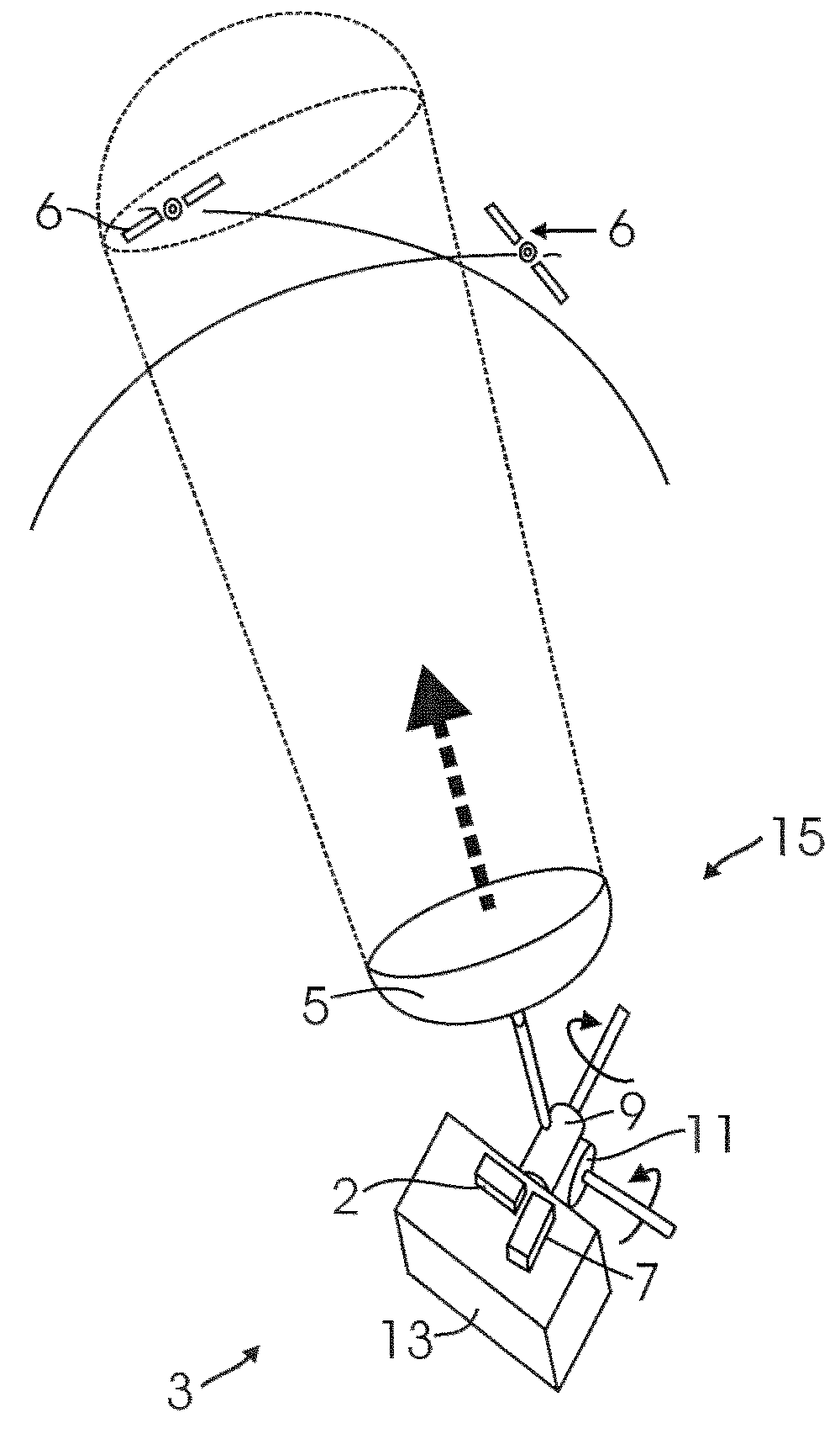
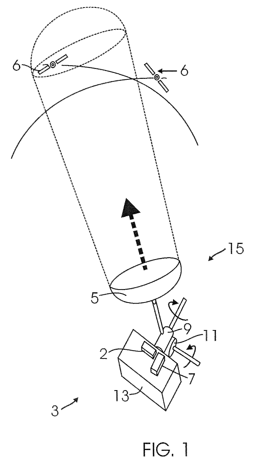
[0022]Broadly, the present invention provides a system and method for attitude determination using a single directionally steered antenna combined with a Global Positioning System (GPS) or Global Navigation Satellite System (GNSS) satellites and receiver system. The GPS / GNSS satellites' locations are known in either or both Earth Center Earth Fixed (ECEF) and Earth Center Inertial (ECI) frames which provide true references for estimating the attitude of a platform vehicle relative to either of these coordinate frames.

[0023]The vehicle platform's location is also known in either or both the ECEF or ECI coordinate system. Thus, the direction vector from t...


PUM


Abstract

A system and method for determining the attitude of a platform is provided. The method includes: (a) Searching and scanning for one or more GPS satellite(s) to determine initial platform position; wherein a single directionally steered antenna scans for the GPS / GNSS satellite; (b) pointing and scanning the antenna to GPS / GNSS satellite to determine a first angular measurement of a direction of a GPS / GNSS signal; (c) measuring carrier to noise ratio of the GPS / GNSS satellite; (d) dithering the single directionally steered antenna to obtain an angular measurement relative to an antenna pattern bore-sight reference; (e) repeating steps (b)-(d) to determine a second angular measurement of the direction of a second GPS signal; (f) determining the attitude error of the platform using the first and second angular measurements; (g) updating the platform position and attitude.

Description

CROSS REFERENCE TO RELATED APPLICATIONS[0001]NoneBACKGROUND[0002]1. Field of Invention[0003]The present invention relates generally to attitude determination systems, and more particularly, to an attitude determination method and system using a single directionally steered antenna and Global Navigation Satellite Systems to determine the attitude of a platform vehicle.[0004]2. Background of the Invention[0005]An attitude determination system is used to estimate the attitude of a platform vehicle, such as a satellite, an aircraft or a ground vehicle. Typically, the attitude determination system references a platform vehicle coordinate system relative to a known reference object in space, such as the earth, the sun satellites, stars or planets, to determine the orientation of the platform relative to a second coordinate system in which in the direction to the object is known (e.g., antenna boresight). The object's known location could be in either inertial or moving reference frame coo...

Claims


Application Information

Patent Timeline
Patent Type & Authority Patents(United States)
IPC IPC(8): G01S5/14G01S19/53
CPCG01S19/53
Inventor TEKAWY, JONATHAN A.DIESPOSTI, RAYMOND S.
Owner THE BOEING CO
Why Eureka
Try Eureka