Biped robot control system

a robot control and robot technology, applied in the direction of electric programme control, program control, instruments, etc., can solve the problems of not being able to avoid collision with and not being able to avoid collision with humans and other bodies that move freely within the walking environmen

Active Publication Date: 2008-07-08
HONDA MOTOR CO LTD
View PDF8 Cites 17 Cited by
  • Summary
  • Abstract
  • Description
  • Claims
  • Application Information

AI Technical Summary

Benefits of technology

[0007]An aspect of this invention is therefore to overcome the foregoing drawback by providing a biped robot control system that can prevent collision with moving objects.

Problems solved by technology

Although this known system can prevent collision with obstacles (stationary objects) registered in advance it cannot avoid collision with obstacles other than the registered ones and, in particular, cannot avoid collision with humans and other bodies that move freely within the walking environment.

Method used


Image

  • Biped robot control system
  • Biped robot control system
  • Biped robot control system

Examples


Embodiment Construction

[0026]A biped robot control system according to an embodiment of this invention will now be explained with reference to the attached drawings.

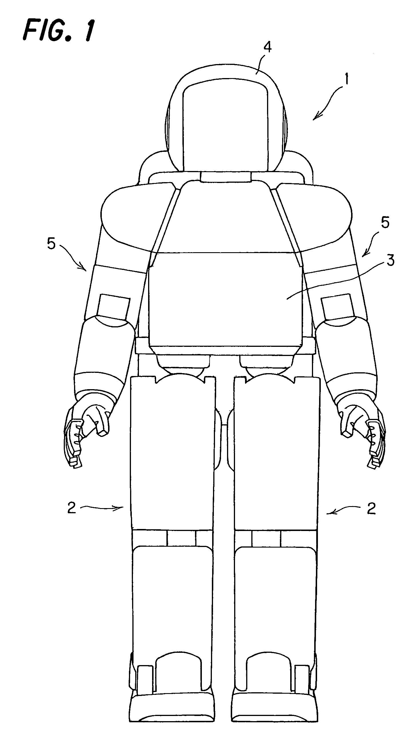
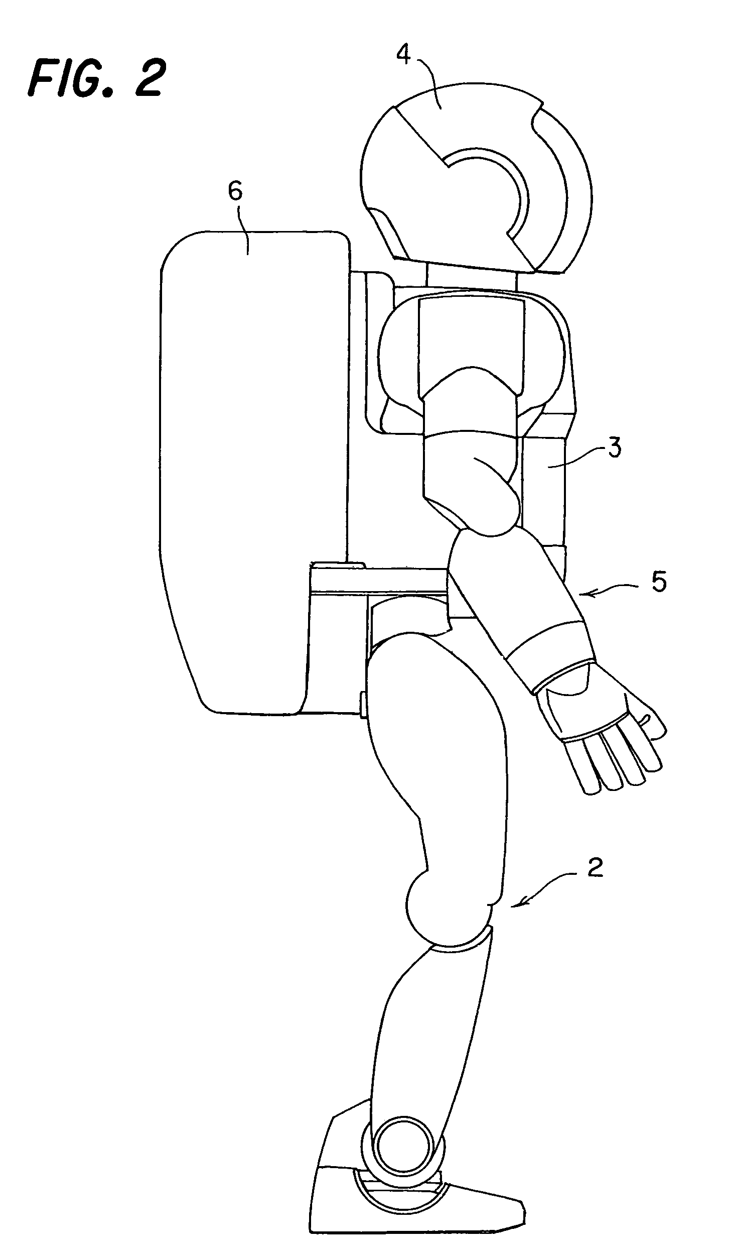
[0027]FIG. 1 is a front view of a biped robot (hereinafter called “robot”) 1 according to an embodiment of this invention, and FIG. 2 is a side view thereof.

[0028]As shown in FIG. 1, the robot 1 is equipped with two legs 2, above which is provided a body (main unit) 3. A head 4 is provided at the upper part of the body 3 and two arms 5 are connected to opposite sides of the body 3. Further, as shown in FIG. 2, a housing unit 6 is provided on the back of the body 3. The housing unit 6 accommodates, among other components, an ECU (electronic control unit; explained later) and a battery power supply (not shown) for the electric motors that drive the joints of the robot 1. The robot 1 shown in FIGS. 1 and 2 is equipped with covers for protecting its internal structure.

[0029]The internal structure of the robot 1 will now be explained with reference...


PUM


Abstract

In a biped robot control system, stereoscopic images captured by CCD cameras are analyzed, the analyzed images are then utilized to detect presence of any moving object around the robot and if it present, to calculate moving object information, and based on the calculated moving object information, it is determined whether or not walking of the robot needs to be stopped. If it is determined to be stopped, the robot is controlled to stop within a period that brings the travel distance at stopping (distance moved between image capture by the CCD cameras and stopping of robot walking) to within a predetermined distance. With this, when the robot approaches a moving object during walking, it can be stopped within the predetermined distance to avoid collision with the moving object.

Description

CROSS REFERENCE TO RELATED APPLICATIONS[0001]This application claims priority of Japanese Patent Application No. 2003-095484, filed on Mar. 31, 2003, the entire contents of which are incorporated herein by reference.BACKGROUND OF THE INVENTION[0002]1. Field of the Invention[0003]This invention relates to a biped robot control system, particularly to a biped robot control system that detects moving objects such as obstacles and human beings from captured images and controls the driving of leg members in accordance with the position of the detected moving objects.[0004]2. Description of the Related Art[0005]One known biped robot control system that controls the driving of leg members based on captured images is described in Japanese Patent No. 3176701 (see paragraphs 0013-0027, for example). The system taught by this patent stores a walking environment map including obstacles in a ROM (read-only memory) beforehand, ascertains its own (the robot's) position in the environment in which ...

Claims


Application Information

Patent Timeline
Patent Type & Authority Patents(United States)
IPC IPC(8): G05D1/02B25J13/00B25J19/00B25J9/16A63H11/00B25J5/00B25J13/08G06K9/00G06N3/00G06T1/00G06T7/20
CPCG06N3/008G06K9/00348G06V40/25
Inventor HIGAKI, NOBUOSHIMADA, TAKAMICHI
Owner HONDA MOTOR CO LTD
Why Eureka
Try Eureka