Self-calibrating time code generator

a time code and generator technology, applied in the field of self-calibrating time sources, can solve the problems of time delay dynamic variation, inherent time delay, and time delay of time source implementation

Active Publication Date: 2008-07-08
SCHWEITZER ENGINEERING LABORATORIES
View PDF30 Cites 38 Cited by
  • Summary
  • Abstract
  • Description
  • Claims
  • Application Information

AI Technical Summary

Problems solved by technology

As a result, such devices often synchronize their measurement activities to a time code generator.
Implementation of a time source often introduces inherent time delays.
That is, the design of, and the components used to implement the time source are often responsible for inherent time delays during operation.
Noise coupling into the time source, and loading or line-induced delays may also contribute to time delays.
In addition, the time delays may dynamically vary over time, due to temperature variations or component aging.
Such delays directly reduce the time accuracy and therefore the performance of the devices requiring the time information.

Method used


Image

  • Self-calibrating time code generator
  • Self-calibrating time code generator
  • Self-calibrating time code generator

Examples


Embodiment Construction

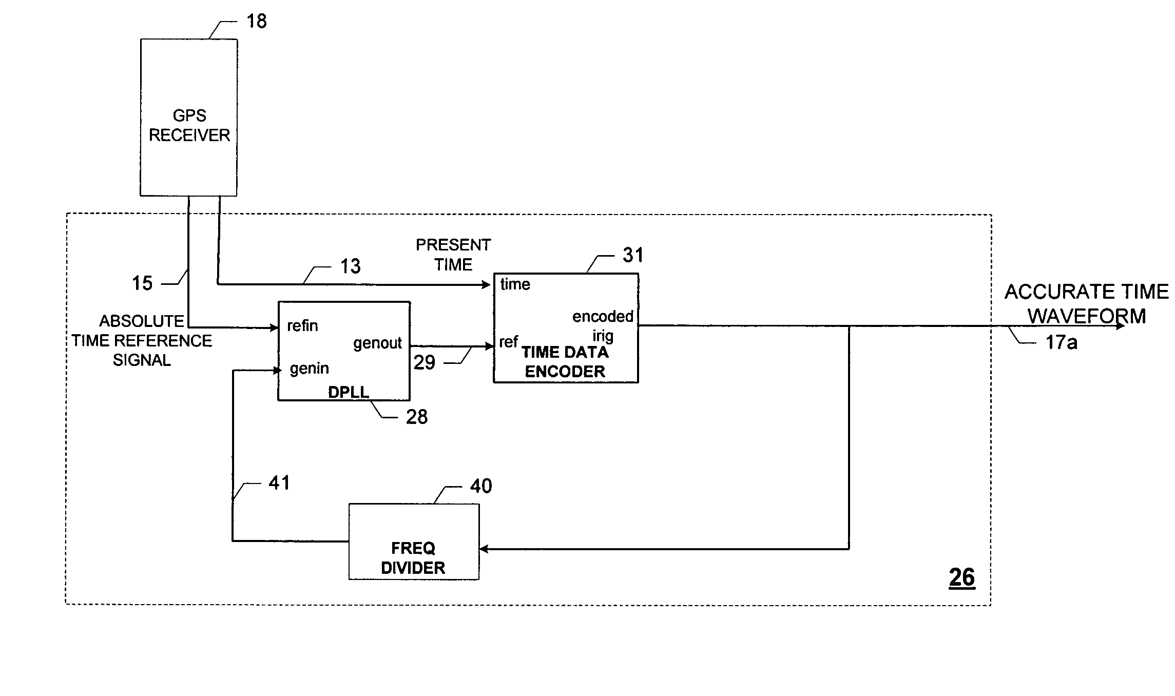
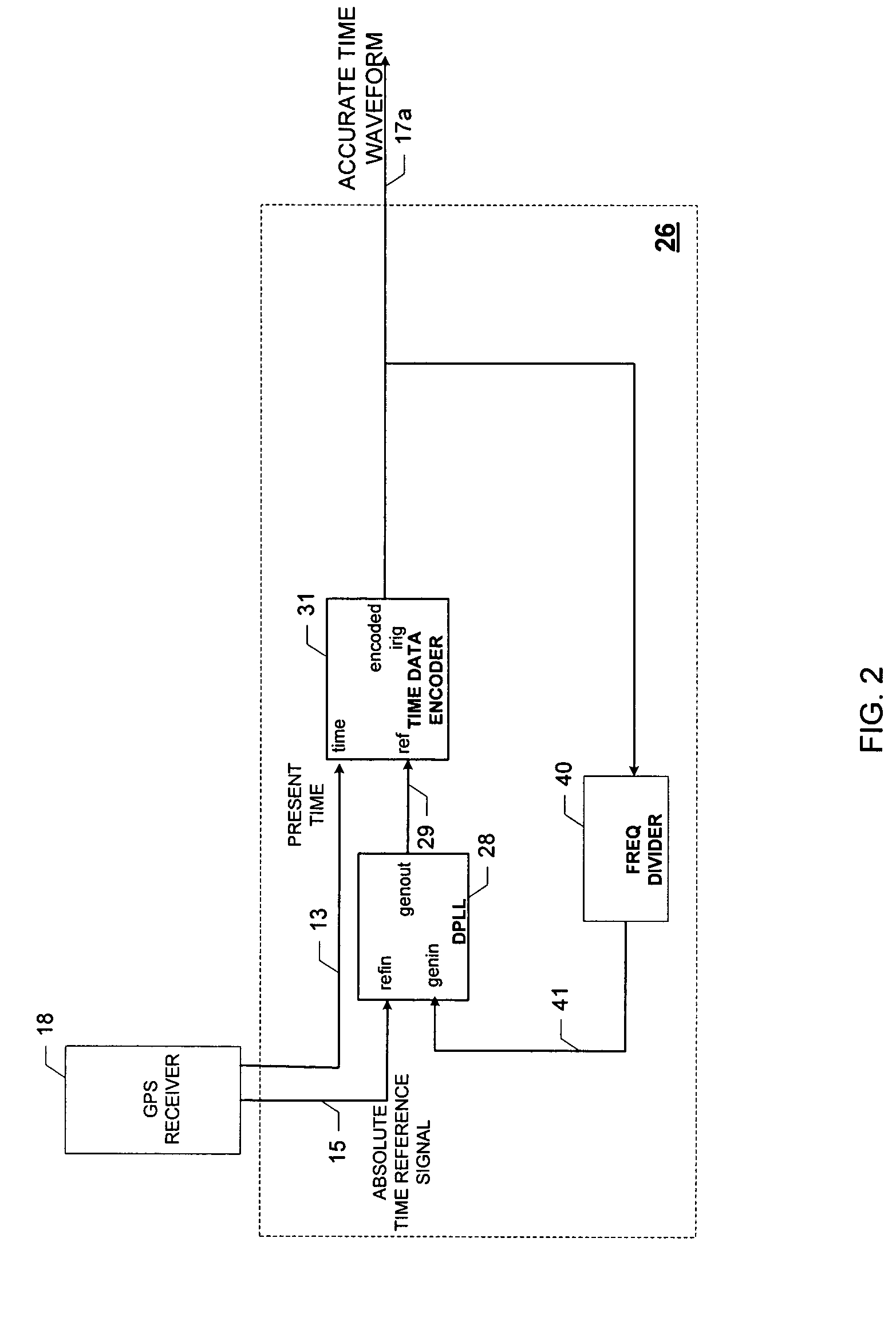
[0017]Unlike prior art methods where, for example, delay corrections are used to correct delays due to satellite transmission of the absolute time reference signal, the self-calibrating time code generators described herein corrects any delays, in real-time, due to distribution of the accurate digital IRIG waveform.

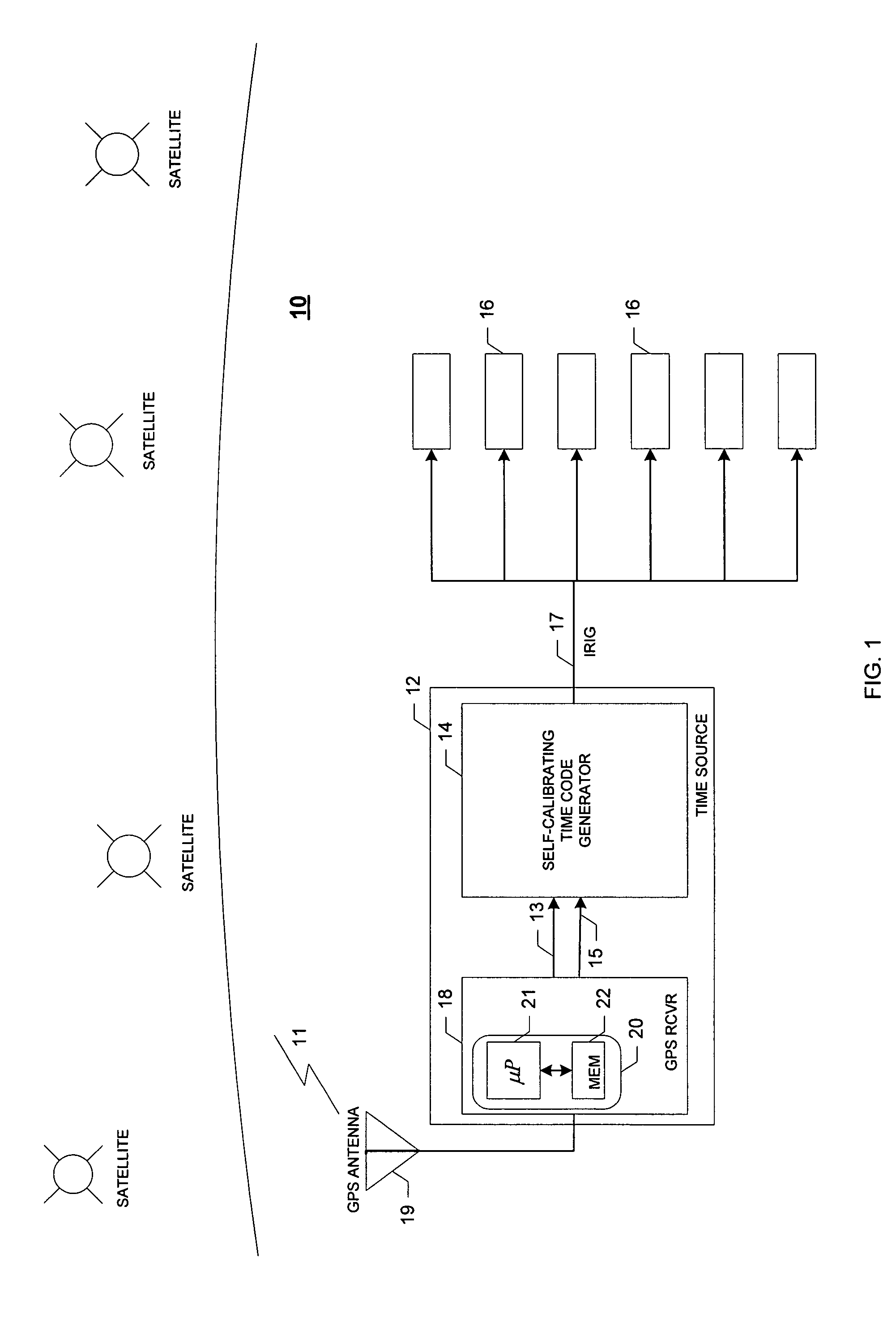
[0018]FIG. 1 is a block diagram of a time source system 10 according to an embodiment of the invention. The time source system 10 includes a time source 12 configured to generate an accurate time waveform suitable for timing and synchronization use by one or more device(s) 16. Such an accurate time waveform may be used by the device(s) 16 to, for example, provide accurate “time stamps” for events monitored and recorded by the device(s) 16, or enable synchronization for a group of devices 16. Although discussed below as a digital IRIG waveform or a conditioned (modulated) analog IRIG waveform, the accurate time waveform is hereinafter referred to as the IRIG waveform 17 (I...


PUM


Abstract

Provided is a self-calibrating time code generator and method for generating an accurate time code (e.g., an accurate IRIG waveform). The self-calibrating time code generator includes a phase-locked loop configured to provide a generated output signal based on a phase difference between an absolute time reference signal and a compensated generated input signal, an IRIG encoder configured to couple a present time value with the generated output signal to form an IRIG waveform, a delay difference indicator configured to provide a time interval value based on a comparison of corresponding pulse edges of the generated output signal and the IRIG waveform, and a numerical delay component configured to delay the generated output signal by the time interval value to form the compensated generated input signal used to time-align the IRIG waveform with the absolute time reference signal to form the accurate IRIG waveform.

Description

CROSS-REFERENCE TO RELATED APPLICATIONS[0001]NoneBACKGROUND OF THE INVENTION[0002]The present invention generally relates to self-calibrating time sources, and more specifically, to a self-calibrating time code generator that dynamically compensates for time delays to generate an accurate time code waveform.[0003]A self-calibrating time source may be used to provide calendar and time-of-year information to a variety of devices for a variety of reasons. For example, sequential events recorders record occurrences of events, and then store a record of each occurrence in a report. The time of the occurrence of each event is also included with the event in the report. The time of the occurrence stored for each event is often derived from a time code generator. Thus, the more accurate the self-calibrating time source, the more accurate the recorded time of each event occurrence in the report.[0004]Self-calibrating time sources may also be used to provide synchronization for various device...

Claims


Application Information

Patent Timeline
Patent Type & Authority Patents(United States)
IPC IPC(8): G06F1/12
CPCH03L7/08G04R40/02H03L7/081
Inventor ZWEIGLE, GREGARY C.BENNETT, JERRY J.ACHANTA, SHANKAR V.
Owner SCHWEITZER ENGINEERING LABORATORIES
Why Eureka
Try Eureka