Control device for engine valve and control system for engine
a control device and control system technology, applied in the direction of valve arrangement, gearing, belt/chain/gearing, etc., can solve the problems of deterioration in the controllability of the feedback control, and a large amount of work is required for the adaptation of the holding learning value, so as to achieve accurate maintenance of controllability in the rotational phase difference and increase adaptation work
- Summary
- Abstract
- Description
- Claims
- Application Information
AI Technical Summary
Benefits of technology
Problems solved by technology
Method used
Image
Examples
first embodiment
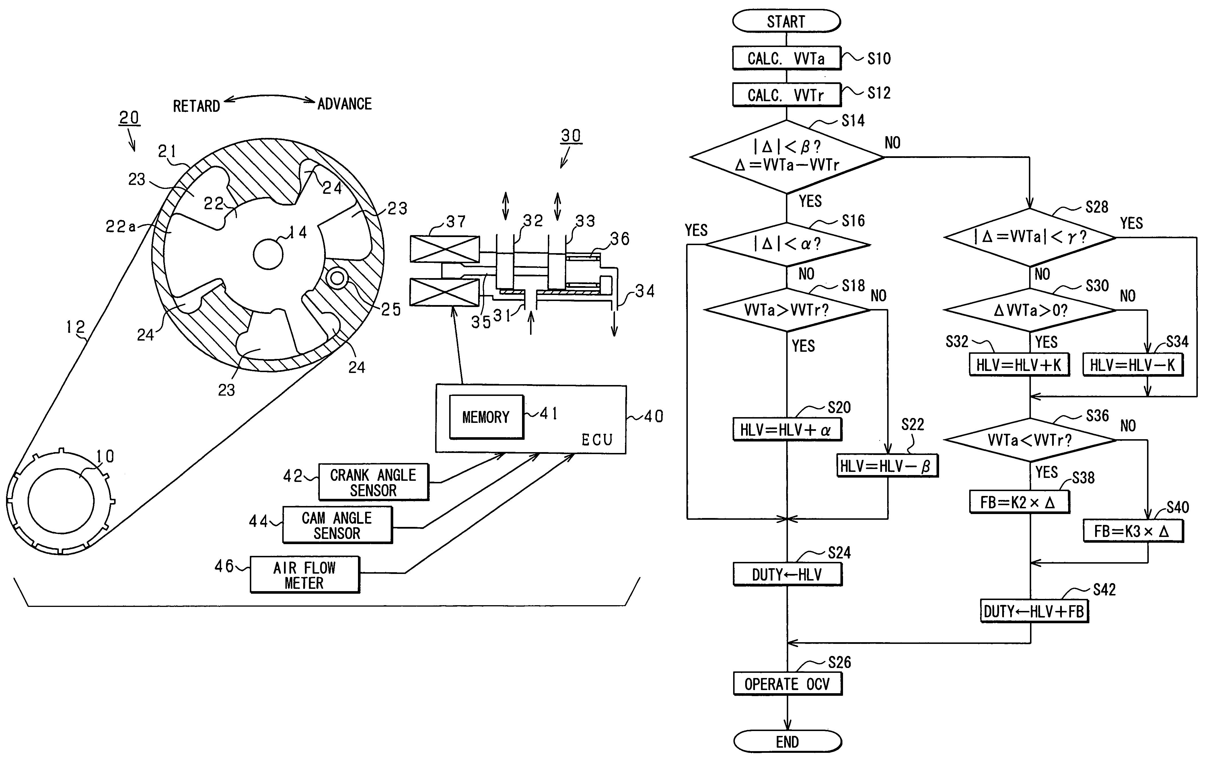
[0026]A first embodiment where a control device and a control system for an engine valve according to the present invention are applied to a gasoline engine will be hereinafter described with reference to the accompanying drawings.
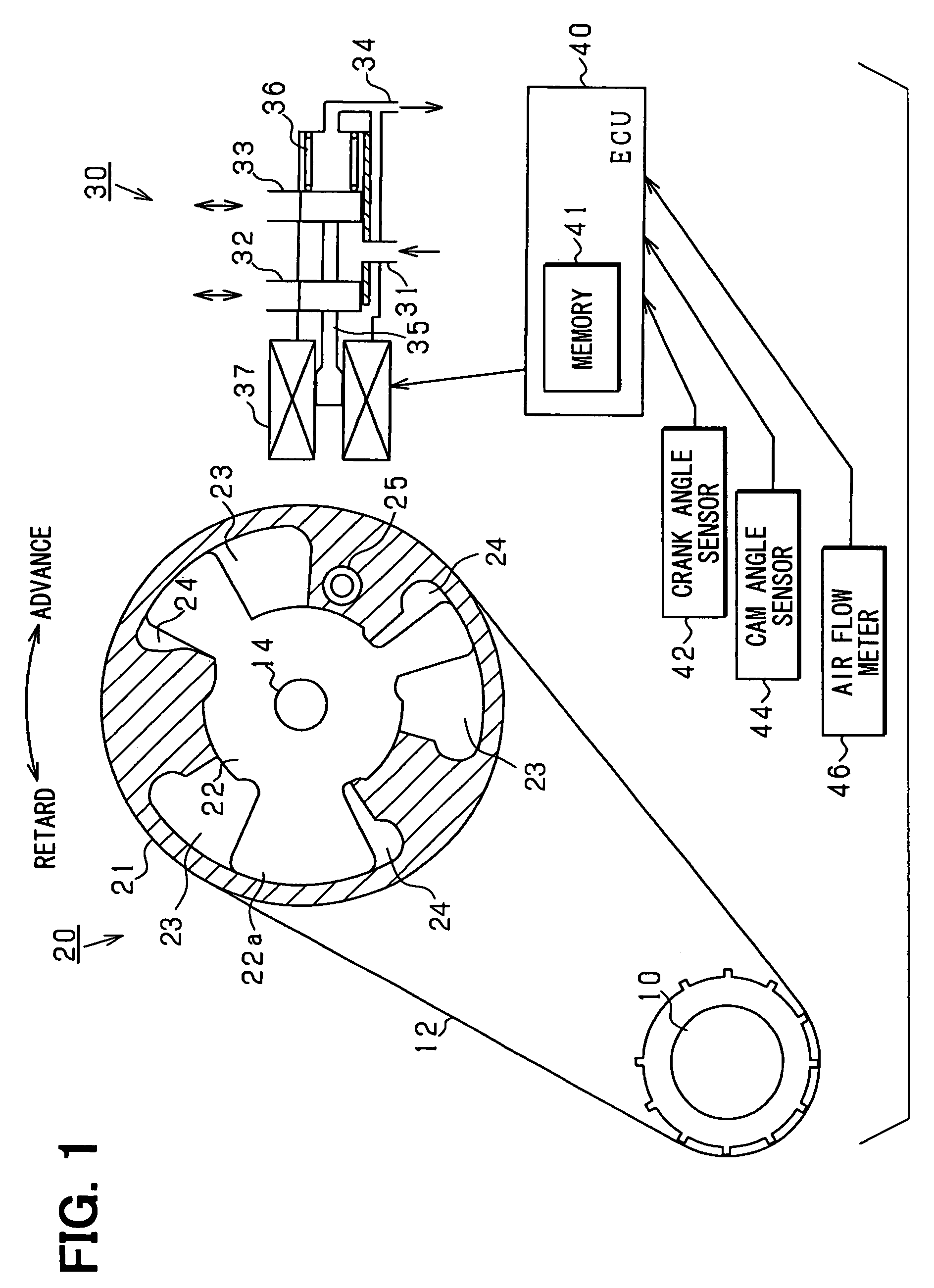
[0027]FIG. 1 shows an entire structure of a control system for an engine valve in the first embodiment.
[0028]As shown in FIG. 1, power of crankshaft 10 is transmitted through a belt 12 and a variable valve timing mechanism 20 to a camshaft 14. The variable valve timing mechanism 20 is provided with a first rotational element 21 connected mechanically to the crank shaft 10 and a second rotational element 22 connected mechanically to the cam shaft 14. In addition, in the first embodiment, the second rotational element 22 is provided with a plurality of projections 22a and also is accommodated in the first rotational element 21. Further, a retard chamber 23 and an advance chamber 24 are defined between the projection 22a of the second rotational element 22 an...
second embodiment
[0063]Mainly a difference of the second embodiment from the first embodiment will be hereinafter described with reference to the accompanying drawings.
[0064]FIG. 6 shows a routine of control for a rotational phase difference between a camshaft and a crankshaft in the second embodiment. This routine is repeatedly executed for example, in a predetermined cycle by the ECU 40. The processes in FIG. 6 which are the same as those in FIG. 3 are referred to as the same step numbers for convenience.
[0065]In the second embodiment, when it is determined in step S28 shown in FIG. 3 described before that the absolute value of the changing amount in the target advance value VVTa is more than the predetermined value γ, the HLV is variably set in response to the changing amount in the target advance value VVTa. This is because since the changing amount of the target advance value VVTa is defined by a changing degree of an engine operating condition, the changing degree of the engine operating condi...
third embodiment
[0068]Mainly a difference of the third embodiment from the second embodiment will be hereinafter described with reference to the accompanying drawings.
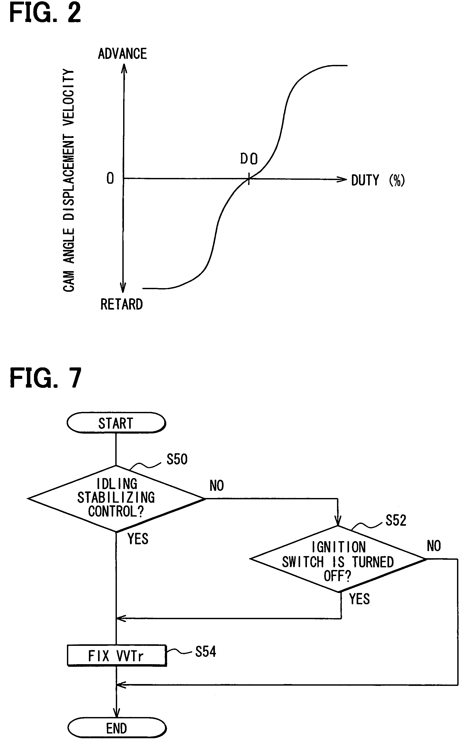
[0069]At the operating of the engine, the target advance value VVTa is basically calculated in step S10 previously shown in FIG. 6 and the actual advance value VVTr is controlled to follow the target advance value VVTa. However, the control to the target advance value VVTa is not always performed in fact and as shown in FIG. 7, there is a case where the actual advance value VVTr is fixed to the maximum retard position.
[0070]FIG. 7 shows a routine of control for an actual advance value VVTr in the third embodiment. This routine is repeatedly executed for example, in a predetermined cycle by the ECU 40.
[0071]In a series of processes in this routine, an actual advance value VVTr is controlled to be fixed to the maximum retard position when an idling stabilizing control is performed (step S50: YES) and an ignition switch is switched to be...
PUM
 Abstract
Description
Claims
Application Information
 - R&D
- Intellectual Property
- Life Sciences
- Materials
- Tech Scout
- Unparalleled Data Quality
- Higher Quality Content
- 60% Fewer Hallucinations
Browse by: Latest US Patents, China's latest patents, Technical Efficacy Thesaurus, Application Domain, Technology Topic, Popular Technical Reports.
© 2025 PatSnap. All rights reserved.Legal|Privacy policy|Modern Slavery Act Transparency Statement|Sitemap|About US| Contact US: help@patsnap.com


