
Rotating barrel storage system

a barrel and storage technology, applied in the field of storage systems, can solve the problems of few aesthetically pleasing options, and achieve the effects of stable separation, stable mounting, and non-interfering separation

Active Publication Date: 2008-07-15
MCNULTY JOHN M
View PDF21 Cites 15 Cited by
  • Summary
  • Abstract
  • Description
  • Claims
  • Application Information

AI Technical Summary

Benefits of technology

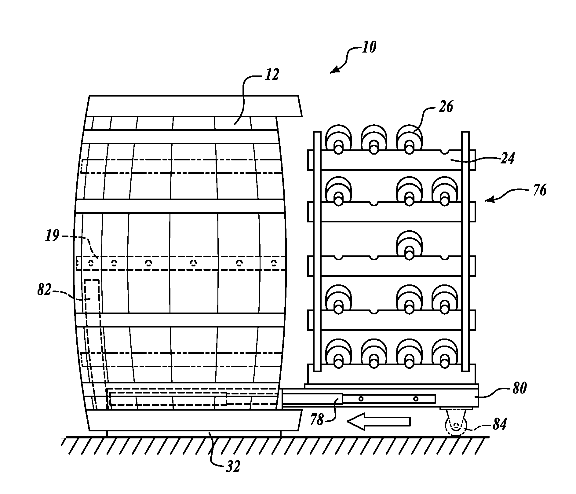
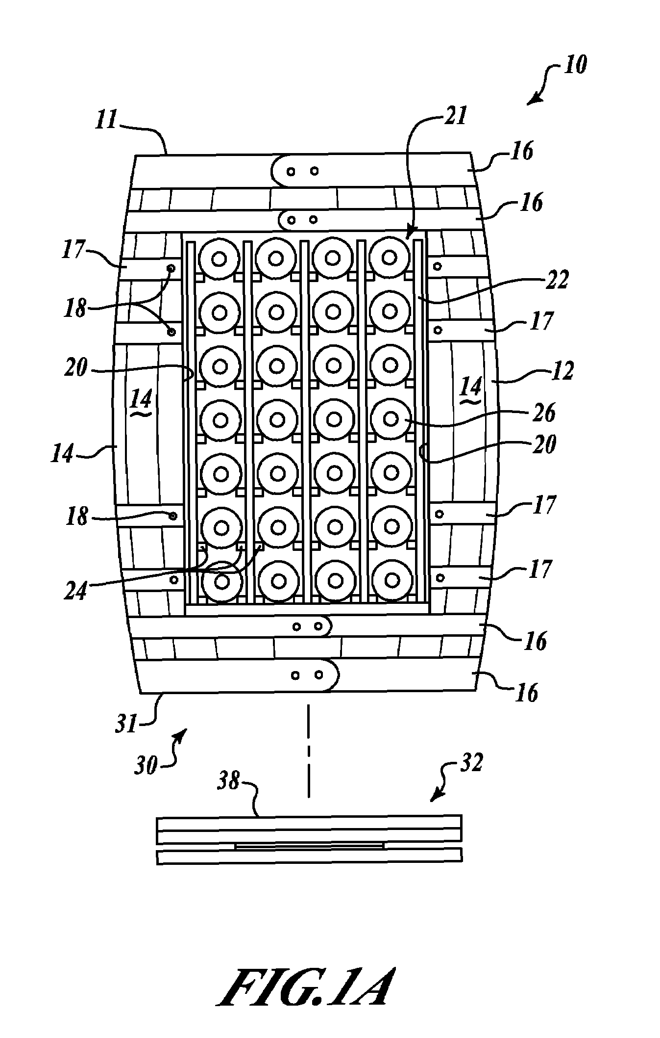
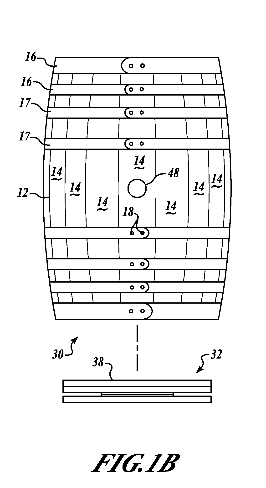
[0010]The wine barrel is fitted onto a specially sized rotating platform comprising a custom-made turntable mechanism, preferably including two circular disks, typically made of wood, such as plywood, chipboard, MDF or press-board. The base of most wine and spirits barrels is about 22″, and the following assembly fits easily inside the recessed bottom of most barrels.
[0011]Two, approximately 20″ diameter disks are placed one above the other, with ball bearing turntable hardware (typically 6″ for 500 pound load limit, or 12″ for 1000 pound load limit) centered, between the two disks. For a strong, non-drag clearance of approximately ¼″ that must be maintained between the metal plates of the turntable, it is preferred to use flat-head elevator or connector bolts, lock washers and nuts to fasten the top ball bearing plate to the top disk, instead of manufacturer-recommended self-tapping sheet metal screws. These bolts provide a better, non-interfering separation between the metal plates of the ball bearing turntable, assuring that adding weight to the barrel will not jam or otherwise adversely impact the turntable function.
[0012]In addition, stabilizing members comprising glide or slide plates, pads or disks (typically ¾″ diameter, HDPE or polytetrafluoroethylene-faced disks specified for up to 1600 pound capacity), ar

Problems solved by technology

For those who make an effort to store the bottles horizontally and away from heat, there are few aesthetically pleasing options besides the open wine rack.

Method used


Image

  • Rotating barrel storage system
  • Rotating barrel storage system
  • Rotating barrel storage system

Examples


Embodiment Construction

[0028]The following detailed description illustrates the invention by way of example, not by way of limitation of the scope, equivalents or principles of the invention. This description will clearly enable one skilled in the art to make and use the invention, and describes several embodiments, adaptations, variations, alternatives and uses of the invention, including what is presently believed to be the best modes of carrying out the invention.

[0029]In this regard, the invention is illustrated in the several figures, and is of sufficient complexity that the many parts, interrelationships, and sub-combinations thereof simply cannot be fully illustrated in a single patent-type drawing. For clarity and conciseness, several of the drawings show in schematic, or omit, parts that are not essential in that drawing to a description of a particular feature, aspect or principle of the invention being disclosed. Thus, the best mode embodiment of one feature may be shown in one drawing, and the...


PUM


Abstract

Storage units of standard, new or used wood stave barrels, mounted on end on a rotating platform and having a side opening cut-out to the interior for access to shelving, drawers, wine racks or other storage devices fitted in the interior. The barrel is mounted on and secured to a rotatable platform that includes a turntable mechanism, the platform being specifically sized to fit inside the base recess of the barrel, so that it is hidden by the barrel lip, yet holds the barrel sufficiently off the ground to clear carpeting or other irregular flooring such as slate, brick or tile pavers, that might otherwise interfere with its rotation. The platform includes friction sliders so that the barrel rotates under hand pressure but does not spin freely. Selected feet or spacer disks are used to provide minimum needed clearance so the barrel appears to float just above the flooring surface.

Description

CROSS REFERENCE TO RELATED APPLICATIONS[0001]This is the Regular US Patent Application of prior Provisional Application Ser. No. 60 / 688,022 filed Jun. 7, 2005 by the same inventor under the same title, the priority of which is claimed under 35 US Code, Sections 119, 120, ff, and the disclosure of which is hereby incorporated by reference.FIELD[0002]The invention relates to storage systems, more particularly to furniture storage units made from standard, new or used wooden liquor, nail, wine, beer or water barrels, mounted on a rotating platform and providing access to the interior for a wide range of shelving, drawers and racks. In the preferred embodiment, used wine barrels contain wine racks which provide a novel enological connection between the barrel's former use of holding wine, and its inventive use for storing bottled wines, spirits or other valuable commodities.BACKGROUND[0003]The use of wine barrels (especially oak barrels) to store and age wine is a centuries old traditio...

Claims


Application Information

Patent Timeline
IPC IPC(8): A47B73/00
CPCA47B73/00
Inventor MCNULTY, JOHN M
Owner MCNULTY JOHN M
Learn More