Ultrasonic irradiation apparatus

a technology of ultrasonic irradiation and irradiation apparatus, which is applied in the direction of mechanical vibration separation, instruments, therapy, etc., can solve the problems of difficult to evenly irradiate the surface of a living body with ultrasonic waves, requires a long time to scan wider areas, and the work load of an operator, such as a doctor, becomes heavier, so as to achieve the effect of easy irradiation

Inactive Publication Date: 2008-07-15
MIWA SCI LAB
View PDF22 Cites 14 Cited by
  • Summary
  • Abstract
  • Description
  • Claims
  • Application Information

AI Technical Summary

Benefits of technology

[0014]An object of the present invention is to provide an apparatus capable of easily irradiating, with ultrasonic waves, a wide area of an object having three-dimensional surfaces.

Problems solved by technology

Therefore, it is difficult to evenly irradiate the surface of a living body with ultrasonic waves.
But, when the scanning area becomes wider, in the conventional system it requires a long time to scan wider areas because of the time required to manually scan the single ultrasonic transducer to accumulate the necessary irradiation dose (intensity of irradiation×the accumulated time of irradiation) per unit surface area.
Hence, the work load for an operator, such as a doctor, becomes heavier.
However, in the case where the area to be scanned is wider, the system disclosed in the published international patent application has the same problems as the conventional ultrasonic irradiation apparatus.
In other words, it takes a long time to scan wider areas and the load imposed on the operator becomes heavier.
As the result, the pressure of the water weight is transferred to the living body, and it is difficult to make adjustments so as to partially support and lessen the pressure due to such weight.
Further, in the apparatus for irradiating with ultrasonic waves via the bag containing the ultrasonic conducting medium, the position of the living body to be irradiated with ultrasonic waves is limited because, if the irradiation direction to the living body is not vertical, the output window of the bag is greatly deformed by gravity and thereby it is difficult to scan smoothly.

Method used


Image

  • Ultrasonic irradiation apparatus
  • Ultrasonic irradiation apparatus
  • Ultrasonic irradiation apparatus

Examples


first embodiment

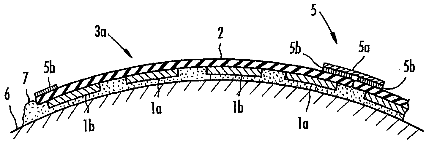
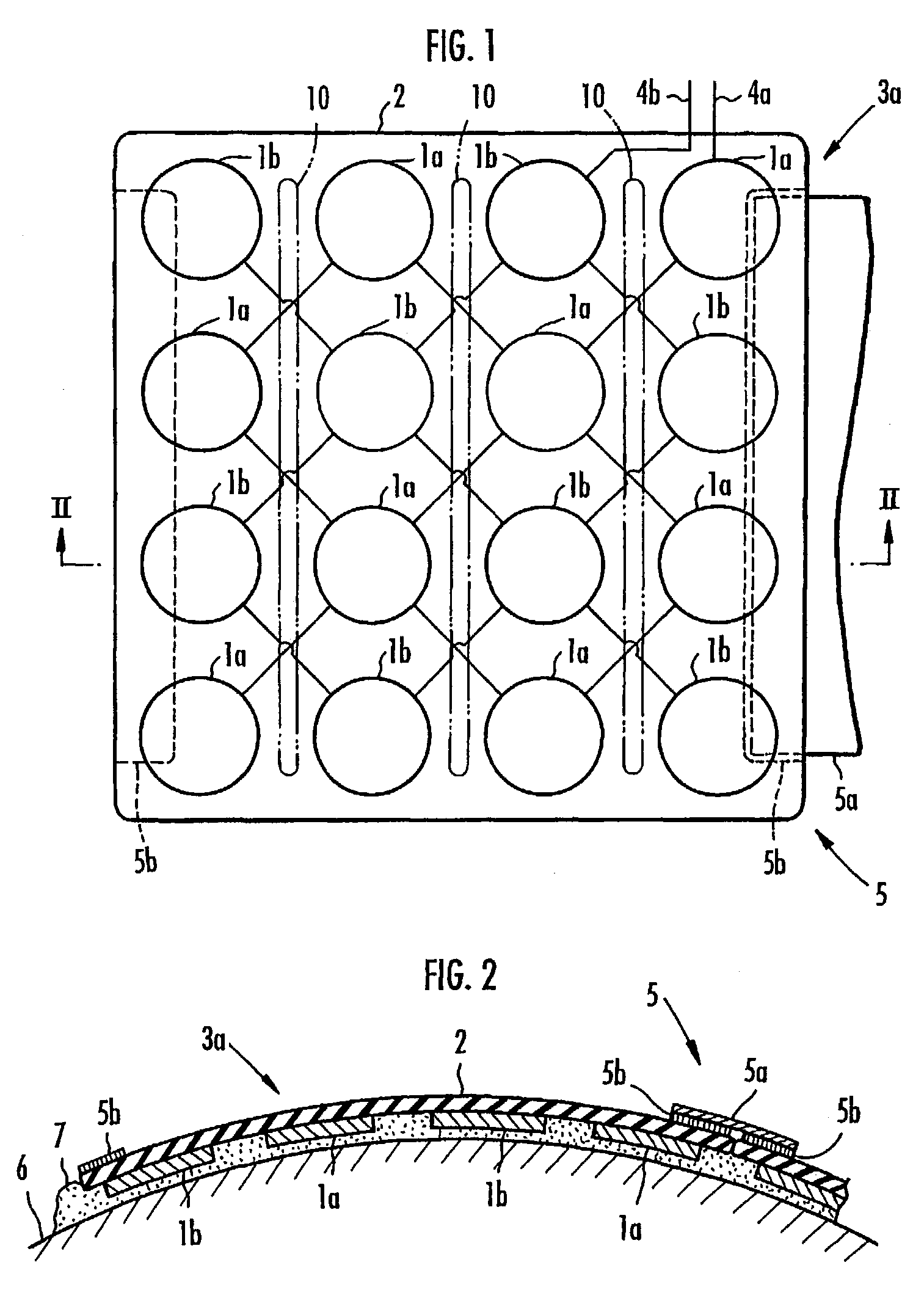
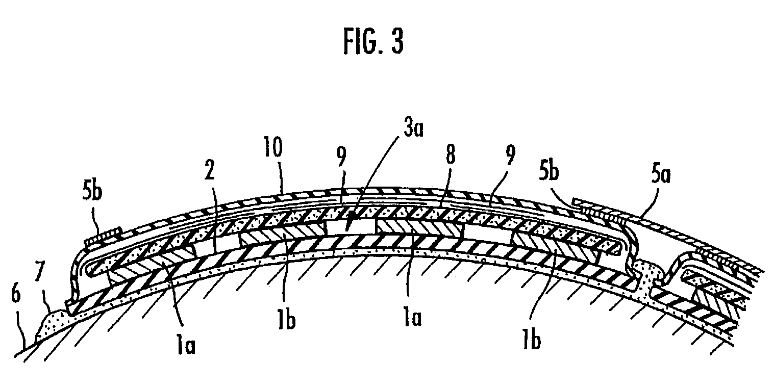
[0062]First, with reference to FIG. 1 through FIG. 3, an ultrasonic irradiation apparatus according to the present invention shall be described.

[0063]The ultrasonic irradiation apparatus, according to this embodiment is an apparatus for irradiating a living body with ultrasonic waves, mainly for lipolysis, but it can be also used for other purposes such as acceleration of the bloodstream, infiltration of an endermic medicine, and so on. In the first embodiment, as shown in FIG. 1, an ultrasonic irradiator 3a comprises a plurality of ultrasonic transducers 1a and 1b installed on one surface of a sheet member 2. In the case where the sheet member 2 is sound-conductive, the ultrasonic transducers 1a and 1b can be appropriately arranged on any of inside and / or outside planes of the sheet member 2.

[0064]The ultrasonic transducers 1a and 1b may be ones having a driving electrode arranged on one plane of a piezoelectric element composed of ceramics (e.g., PZT (Pb(Zr*Ti3)O3), etc.) and an o...

second embodiment

[0096]Next, an ultrasonic irradiation apparatus according to the present invention shall be explained with reference to FIG. 4 through FIG. 7.

[0097]In the ultrasonic irradiation apparatus, an ultrasonic irradiator 3b is composed of a plurality of ultrasonic transducers 1a and 1b installed on a net member 11 and arranged in a plane, as described in FIG. 4. The net member 11 is preferably composed of a material having flexibility and elasticity, wherein the net member 11 is formed of at least one type of material such as a string, a band, a spring, a chain and linked rods that are freely rotatable, and being fastened by knots 12. The ultrasonic transducers 1a and 1b are arranged in a checkered pattern within the net member 11 and are adhered to the net member 11. However, the arrangement of the ultrasonic transducers 1a and 1b is not limited to such a checkered pattern.

[0098]The strings for forming the net member 11 may be, for example, a synthetic resin string, a rubber line (a rubbe...

third embodiment

[0105]Next, referring to FIG. 8 through FIG. 10, an ultrasonic irradiation apparatus according to the present invention shall be explained.

[0106]In the ultrasonic irradiation apparatus of this embodiment, a plurality of ultrasonic transducers 1a and 1b, composed of a driving electrode 22 formed on one plane of a flexible piezoelectric sheet member 21 and an opposed ground electrode 23 formed on the other plane of the flexible piezoelectric sheet member 21, are arranged in a plane facing each other, for forming the ultrasonic irradiator 3c as depicted in FIG. 8. In the ultrasonic irradiator 3c, the ultrasonic transducers 1a and the ultrasonic transducers 1b are alternately arranged in each row of a tessellate arrangement (cross-stripes pattern).

[0107]As the flexible piezoelectric member 21, a sheet of an organic piezoelectric material, like PVDF, or a sheet formed under an electric field from a plastic containing fine-grained piezoelectric ceramic, such as PZT, may be used. The drivi...


PUM


Abstract

An ultrasonic irradiation apparatus irradiates ultrasonic waves onto a wide area having three-dimensionally curved surfaces. An ultrasonic irradiator having a plurality of ultrasonic transducer is arranged in a plane. The position of at least a portion of the ultrasonic transducers is mutually and flexibly changeable in three dimensions. Ultrasonic transducers are installed on a surface of a flexible and / or elastic sheet member or net member. The ultrasonic irradiator may include a plurality of ultrasonic transducers formed on a flexible piezoelectric sheet member, including driving electrodes arranged on one surface and opposed electrodes arranged on another surface. The ultrasonic irradiator may be installed on or inside of a flexible planar bag containing a fluidic ultrasonic conductive medium. A mechanism is provided for moving or tilting the ultrasonic irradiator with respect to the object, or a band-holding member may be provided for fitting the irradiator to the object.

Description

CROSS-REFERENCE TO RELATED APPLICATION[0001]This application is the U.S. national phase of PCT application number PCT / US01 / 16929, filed May 24, 2001, which further claims priority to U.S. patent application Ser. No. 09 / 578,024, filed May 24, 2000.TECHNOLOGICAL FIELD[0002]The present invention relates to an ultrasonic irradiation apparatus for irradiating, with ultrasonic waves, a wide area of an object to be irradiated such as a living body.BACKGROUND ART[0003]The inventor of the present invention conducted research and discovered that fats within a living body were decomposed (lipolysis) by irradiating the living body with ultrasonic waves having a specific frequency. A patent application regarding an ultrasonic wave irradiation apparatus was filed and published as PCT Publication Number WO 99 / 39677 on Aug. 12, 1999.[0004]In the practice of the previous invention, it was required to irradiate the living body with ultrasonic waves. The living body has wide three-dimensionally curved...

Claims


Application Information

Patent Timeline
Patent Type & Authority Patents(United States)
IPC IPC(8): A61H1/00A61H1/02A61H5/00A61B17/22A61B18/00A61N7/00B06B1/06G10K11/00
CPCG10K11/004B06B1/0637B06B1/0688A61N7/00A61B2017/2253A61B2018/00005A61B2018/00041A61N2007/0078A61F7/00A61H23/02B06B1/06H04R17/00
Inventor MIWA, HIROHIDEMIWA, HIROAKIKINO, MASATO
Owner MIWA SCI LAB
Why Eureka
Try Eureka