Time of flight mass spectrometer

a mass spectrometer and time-of-flight technology, applied in mass spectrometers, separation processes, dispersed particle separation, etc., can solve the problems of difficult separation of ions having larger differences in inability to measure the whole range of mass to charge ratios, and inability to integrate a long straight path in tofms. , to achieve the effect of reducing time and labor of mass analysis

Inactive Publication Date: 2008-07-15
SHIMADZU CORP
View PDF9 Cites 3 Cited by
  • Summary
  • Abstract
  • Description
  • Claims
  • Application Information

AI Technical Summary

Benefits of technology

[0010]An object of the present invention is, therefore, to provide a TOFMS that can measure a wide range of mass to charge ratios while providing a long flight distance with a simpler structure.
[0021]According to the time of flight mass spectrometer of the present invention, a mass spectrometry of an ion for a wide range of mass to charge ratio can be made by simply performing two measurements on the same sample. This greatly reduces the time and labor of mass analysis, and a wide range of mass spectrum can be obtained on a scarce sample on which many measurements are impossible.

Problems solved by technology

In many cases, however, it is difficult to incorporate a long straight path in a TOFMS due to the limited overall size, so that various measures have been taken to effectively lengthen the flight length.
It means that, in such a TOFMS, ions having smaller difference in the mass to charge ratio can be adequately separated, but ions having larger difference in the mass to charge ratio are sometimes difficult to separate.
Unless enough amount of sample is available, it is impossible to measure the whole range of mass to charge ratios.
But the same problem as discussed above occurs in such a case.

Method used


Image

  • Time of flight mass spectrometer
  • Time of flight mass spectrometer
  • Time of flight mass spectrometer

Examples


Embodiment Construction

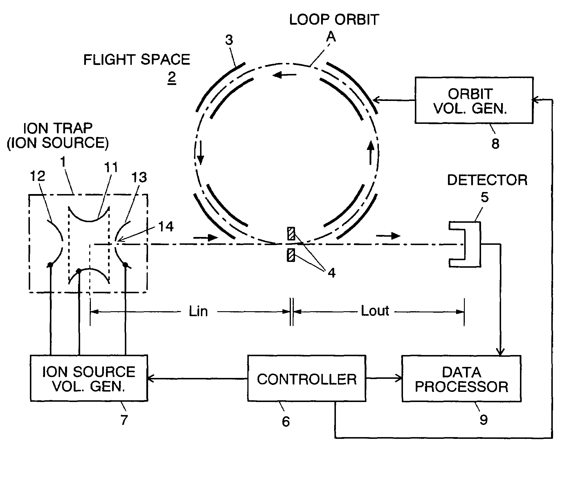
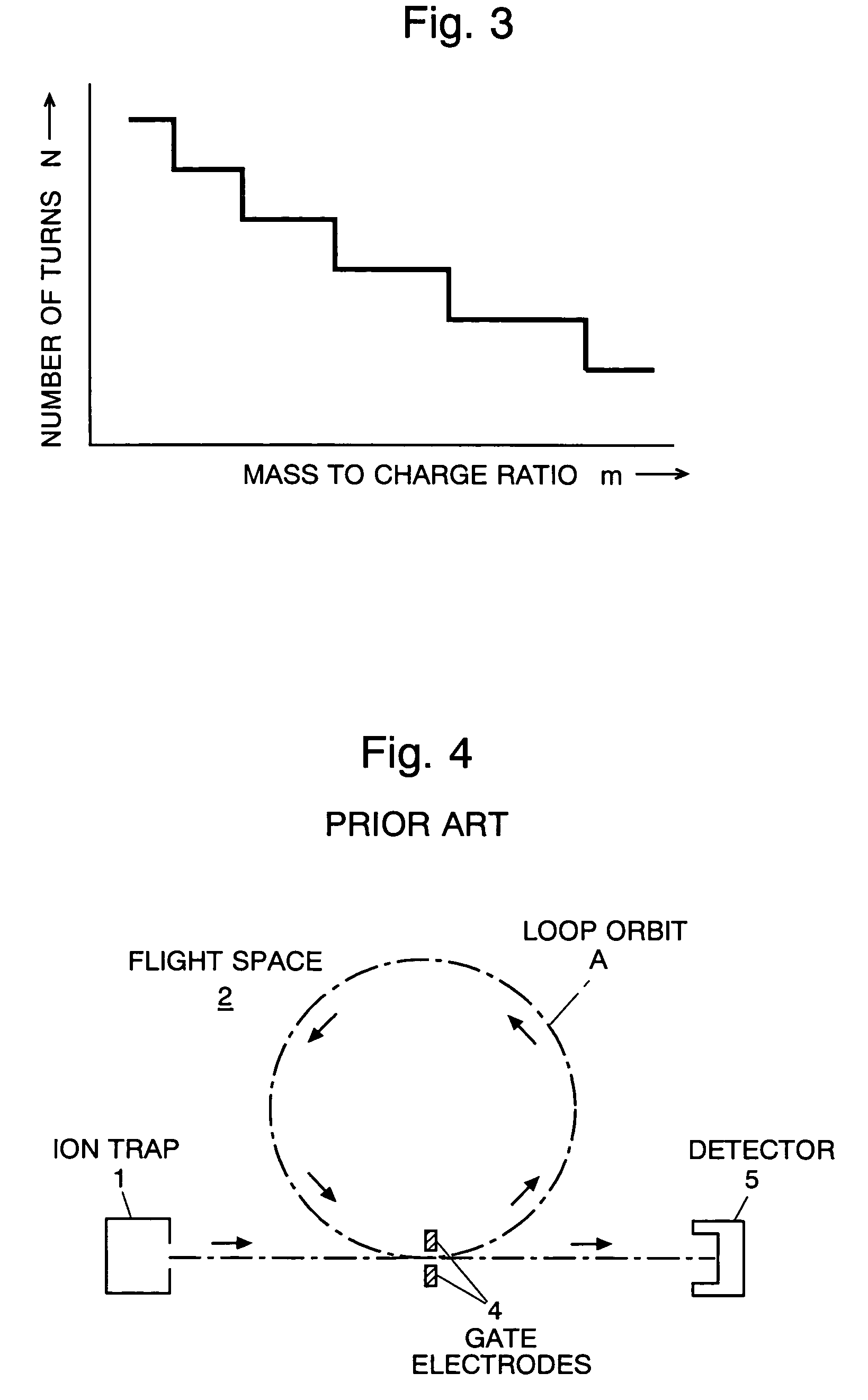
[0028]A TOFMS embodying the present invention is described referring to the attached drawings. FIG. 1 shows a schematic diagram of the TOFMS of the embodiment, in which the same numerals are used for the same elements as shown in FIG. 4.

[0029]The TOFMS of the present embodiment uses a three-dimensional quadrupole ion trap 1 as the ion source. The ion trap 1 is composed of a ring electrode 11 and a pair of end cap electrodes 12, 13 placed opposite each other with the ring electrode between them. Appropriate voltages are applied from an ion source voltage generator 7 to the ring electrode 11 and the end cap electrodes 12, 13 to form a quadrupole electric field for trapping, or containing, ions in the space surrounded by the three electrodes 11, 12 and 13. Ions can be generated inside the ion trap, or they can be generated in another ion source (not shown) outside of the ion trap 1, and introduced into the ion trap 1. The ions trapped in the ion trap 1 are given a certain amount of kin...


PUM


Abstract

A time of flight mass spectrometer according to the present invention includes: a) an ion source at which an ion starts flying; b) an energizer for giving a predetermined amount of energy to the ion to let the ion start flying from the ion source; c) an ion guide for forming a time-focusing flight path on which the ion flies once or repeatedly; d) a detector for detecting the ion after flying the flight path; e) an analysis controller for giving different amounts of energy to ions of the same kind using the energizer, and for measuring the values of the flight time of the ions from the ion source to the detector for the amount of energy; and f) a mass calculator for calculating or estimating the mass to charge ratio of the ion based on the difference in the values of the flight time of the ions. Since the flight time of ions on the time-focusing flight path does not depend on their kinetic energy, the difference in the flight time of an ion having two different amounts of energy gives the estimation of the mass to charge ratio of the ion. Thus, a mass spectrometry of an ion for a wide range of mass to charge ratio can be made by simply performing two measurements on the same sample. This greatly reduces the time and labor of mass analysis, and a wide range of mass spectrum can be obtained on a scarce sample on which many-time measurements are impossible.

Description

[0001]The present invention relates to a time of flight mass spectrometer (TOFMS), especially to one that includes a flight space in which ions to be analyzed fly on almost the same loop orbit or reciprocal orbit repeatedly.BACKGROUND OF THE INVENTION[0002]In a general TOFMS, ions accelerated by an appropriate electric field are injected into a flight space where no electric field or magnetic field is present. The ions are separated by their mass to charge ratios according to the flight time until they reach and are detected by a detector. Since the difference in the flight time of two ions having different mass to charge ratios is larger as the flight path is longer, it is preferable to design the flight path as long as possible in order to enhance the resolution of the mass to charge ratio of a TOFMS. In many cases, however, it is difficult to incorporate a long straight path in a TOFMS due to the limited overall size, so that various measures have been taken to effectively length...

Claims


Application Information

Patent Timeline
Patent Type & Authority Patents(United States)
IPC IPC(8): B01D59/44
CPCH01J49/408
Inventor YAMAGUCHI, SHINICHI
Owner SHIMADZU CORP
Why Eureka
Try Eureka