Voice coil motor apparatus

a voice coil and motor technology, applied in the field of miniaturized voice coil motor equipment, can solve the problems of inability to meet the needs of mass production, inability to meet the needs of production,

Inactive Publication Date: 2008-07-15
VASSTEK INT
View PDF4 Cites 35 Cited by
  • Summary
  • Abstract
  • Description
  • Claims
  • Application Information

AI Technical Summary

Benefits of technology

[0008]The primary objective of the present invention is to proposes a low-cost miniaturized voice coil motor apparatus having a guidance mechanism with a magnetic pre-load and without any free-play in order to overcome the drawbacks and bottlenecks appearing in the application of the conventional voice coil motor to the driving of lens module of the miniaturized camera.
[0009]The voice coil motor apparatus of the present invention is characterized in that the magnetic flux leakage from the voice coil motor itself generates a pre-load on the guidance steel shaft, which enables the friction to be constant and the gap between the contact faces of the moving and non-moving members to be eliminated so that the lens module can has a motion with low friction and high repeatability and without any free-play. The voice coil motor apparatus of the present invention is also characterized in that the voice coil motor has a non-circular but rectangular magnetic structure, which can concentrate the magnetic flux to output maximum force under a given length and width thereof.

Problems solved by technology

However, the application of the conventional voice coil motor to drive the lens module of the miniaturized camera has the following bottlenecks:(a) The lens is a movable piece and driven by the voice coil motor to move back and forth to achieve the objective of auto-focus or variable-focus, which, in addition to a high repeatability of positioning, also demands a high standard about the runout between the motion axis and the optical axis.
If the first method mentioned above is adopted, the accomplishments in the motion repeatability and the friction are superior, but the precision linear bearing is expensive and has a bottleneck in miniaturization.
In the antecedent of mass-producing the miniaturized camera, it is not practical.
If the second method mentioned above is adopted, the image quality of the miniaturized camera will be influenced owing to the runout resulting from the difference in the elastic moduli of the elastic platelets or the difference in the magnetizations of multiple segments of arc type magnets; further, in its application to the portable miniaturized camera, the gravity of lens will also results in motion runout; therefore, adopting the second method will incur a lower yield in mass-production; moreover, the gravity-induced runout will obviously worsen the image quality in the future high-pixel miniaturized camera.
If the third method mentioned above is adopted, the runout of the motion axis is controlled via the confinement of the strict assemblage tolerance between the moving and the non-moving members; however, the precision of the component injection molds are not so uniform and hard to control, which will result in unstable quality in mass-production, wherein the components are assembled randomly and the friction between the moving and non-moving members and the angle of motion runout are variable; too tight tolerance induces too high friction, which further induces the voice coil motor to be hard to drive as the force output by the voice coil motor is so limitary; too loose tolerance induces too large free-play angle, which further induces the image quality to be lowered down.

Method used


Image

  • Voice coil motor apparatus
  • Voice coil motor apparatus
  • Voice coil motor apparatus

Examples


Embodiment Construction

[0019]To enable the technical contents of the present invention to be more easily understood, the detailed description of the present invention is to be stated below in cooperation with the attached drawings.

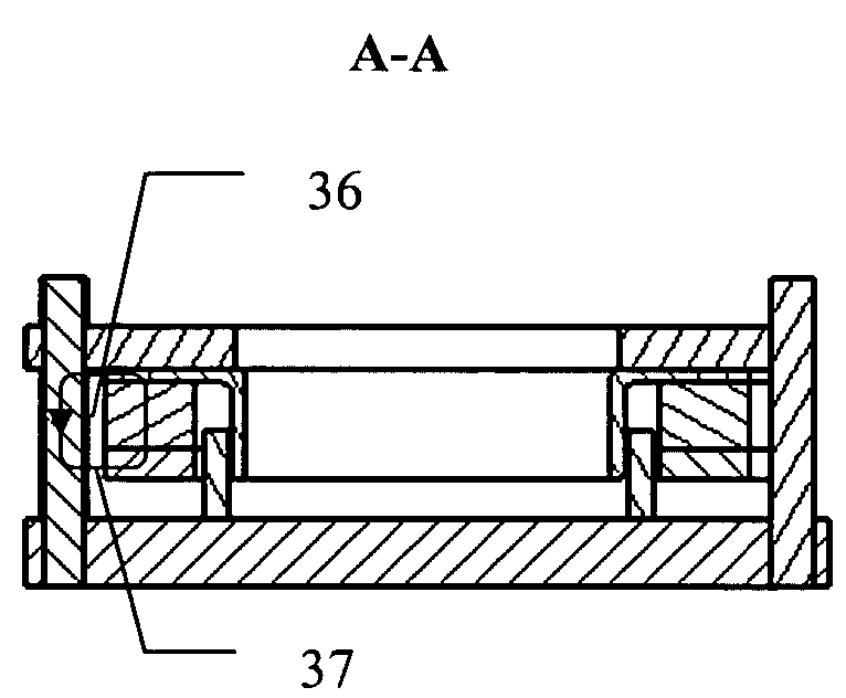
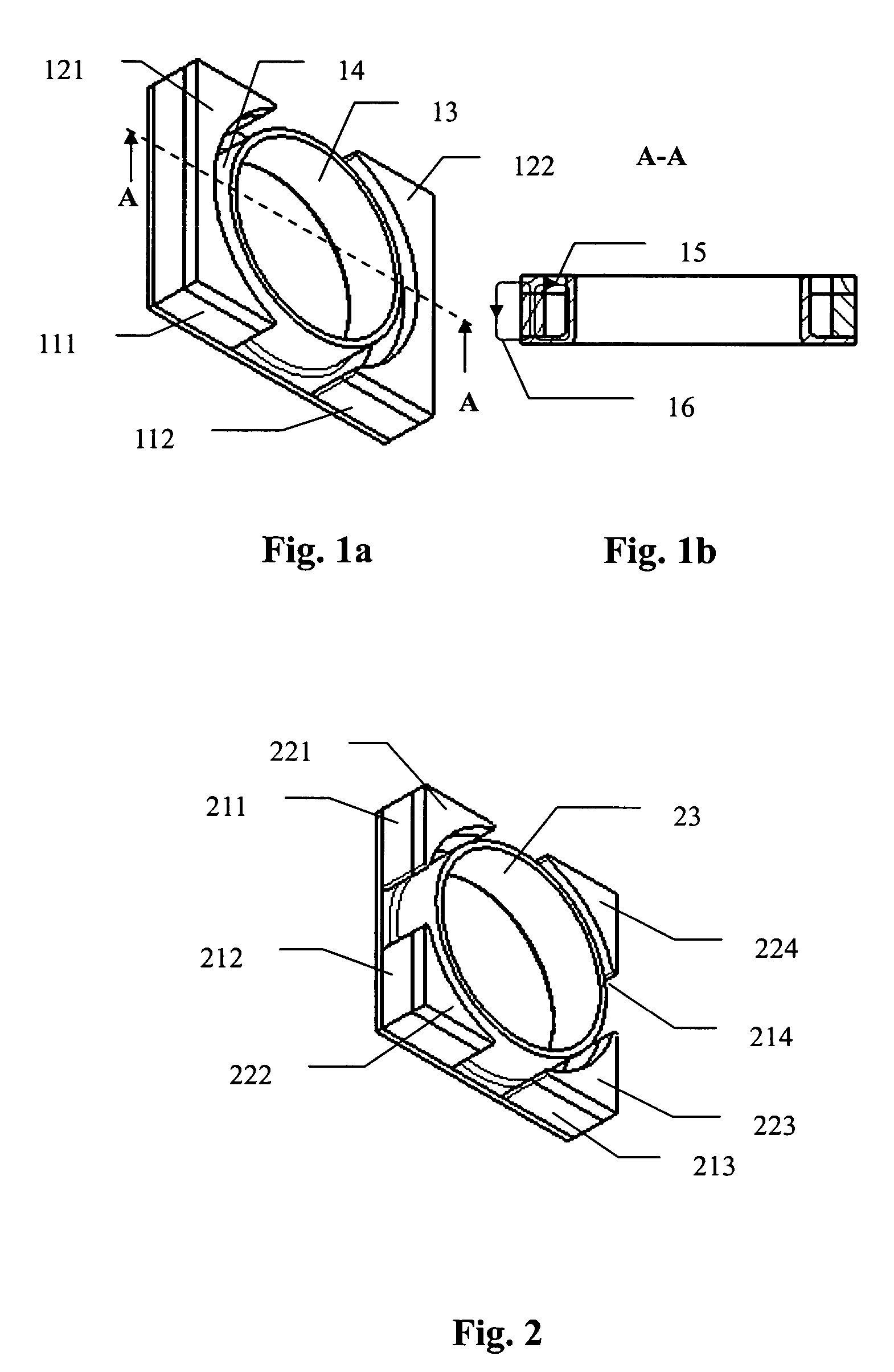
[0020]Referring to FIG. 1a and FIG. 1b, the magnetic structure of the present invention comprises: two non-annular magnets 111 and 112, two non-annular surface yokes 121 and 122, and a bottom yoke 13 with a central annular wall, which are stacked along the moving axis of the voice coil motor. The non-circular magnetic structure has a rectangular contour and forms two closed magnetic loops. One of the closed magnetic loops is the primary magnetic line 15 that generates the thrust, and the primary magnetic line 15 proceeds from the upper surface of the non-annular magnets 111 or 112 and through the non-annular surface yoke 121 or 122 and cross an inner annular gap 14 to reach the central annular wall of the bottom yoke 13 and then is guided by the bottom yoke 13 back to the lower ...


PUM


Abstract

A voice coil motor apparatus applied to an auto-focus or variable-focus lens module of a miniaturized camera includes: a voice coil motor, a plurality of steel guidance shafts, a lens holder, and a base. The voice coil motor also includes a magnetic part including magnets and yokes, and an electrical part including a coil winding. The magnetic part is rigidly coupled to the lens holder to form the moving member. The electrical part and the steel guidance shafts are fixed on the base to form the non-moving member. The pre-loaded force due to the interaction between the leakage flux of the magnetic part and the steel guidance shafts eliminates the free-play resulting from the tolerance gap between the moving and the non-moving members, and that the magnets and the yokes form a non-circular magnetic structure having a rectangular contour in order to minimize the overall dimension.

Description

BACKGROUND OF THE INVENTION[0001]1. Field of the Invention[0002]The present invention relates to a miniaturized voice coil motor apparatus with a magnetically pre-loaded precision guidance, particularly to a voice coil motor apparatus, which drives the lens module of miniaturized camera.[0003]2. Description of the Related Art[0004]As shown in FIG. 5, the conventional cylindrical voice coil motor comprises: a concentric yoke 51 having a U-shape section; multiple segments of arc-type magnets 52, which is attached to the inner face of the U-shape sectional concentric yoke 51 to form a closed magnetic field; and a coil 53, disposed inside the gap 54 between the magnet 52 and the yoke 51; wherein a current flowing through the coil 53 will interact with the magnetic field inside the gap 54, which will generate a thrust. In order to maintain the uniformity of the spacing between the coil 53 and the magnet 52 and the spacing between the coil 53 and the yoke 51, several methods can be used t...

Claims


Application Information

Patent Timeline
Patent Type & Authority Patents(United States)
IPC IPC(8): H02K41/00
CPCG02B7/02G03B13/34H04N5/2254G11B33/12H02K41/0356G11B5/4806H04N23/55
Inventor TSENG, YU-KUANG
Owner VASSTEK INT
Why Eureka
Try Eureka