Dead time control circuit capable of adjusting temperature characteristics of dead time

a control circuit and dead time technology, applied in logic circuit coupling/interface arrangement, pulse technique, instruments, etc., can solve the problems of dead time, inability to adjust delay time, above-described second prior art dead time control circuit, increase in size and manufacturing cost,

Active Publication Date: 2008-07-15
RENESAS ELECTRONICS CORP
View PDF3 Cites 18 Cited by
  • Summary
  • Abstract
  • Description
  • Claims
  • Application Information

AI Technical Summary

Problems solved by technology

In the above-described first prior art dead time control circuit, however, even when the delay time of the delay circuit fluctuates due to environmental factors such as temperature, power supply voltage, etc., it is impossible to adjust the delay time, i.e., the dead time.
The above-described second prior art dead time control circuit, however, is increased in size and manufacturing cost due to the external resistor and the external capacitor.
Also, since the characteristics of the external resistor and the external capacitor per se fluctuate, it is impossible to accurately control the dead time.

Method used


Image

  • Dead time control circuit capable of adjusting temperature characteristics of dead time
  • Dead time control circuit capable of adjusting temperature characteristics of dead time
  • Dead time control circuit capable of adjusting temperature characteristics of dead time

Examples


Embodiment Construction

[0027]Before the description of the preferred embodiments, prior art dead time control circuits will be explained with reference to FIGS. 1, 2, 3, 4, 5 and 6.

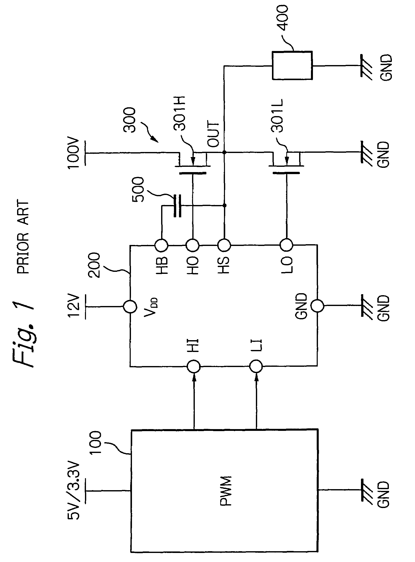
[0028]In FIG. 1, which illustrates a prior art digital audio apparatus, a pulse width modulator 100 powered by a relatively low power supply voltage such as 5V or 3V generates output voltages and transmits them to a high-side input terminal HI and a low-side input terminal LI of a predriver 200 powered by a relatively high power supply voltage such as 12V at its power supply terminal VDD. The predriver 200 generates output voltages at their high-side output terminal HO and low-side output terminal LO and transmits them to a half bridge circuit or a push-pull type output buffer 300 powered by a commercial power supply voltage such as 100V.

[0029]The push-pull type output buffer 300 receives the output voltages at the high-side output terminal HO and the low-side output terminal LO of the predriver 200 to generate an output voltag...


PUM


Abstract

In a dead time control circuit, a delay circuit is connected to an input terminal and adapted to delay signals therethrough by a delay time corresponding to a dead time. A logic circuit has a first input connected via the delay circuit to the input terminal, a second input connected directly to the input terminal, and an output connected to an output terminal. The dead time having adjustable temperature characteristics.

Description

BACKGROUND OF THE INVENTION[0001]1. Field of the Invention[0002]The present invention relates to a dead time control circuit used in a predriver for driving a half bridge circuit or a push-pull type output buffer for driving a load.[0003]2. Description of the Related Art[0004]In a push-pull type output buffer, two switching elements are connected between a power supply terminal and a ground terminal. When the switching elements are alternately turned ON and OFF to drive a load connected thereto, if the switching elements are simultaneously turned ON, a large penetration current flows through the push-pull type output buffer, so that the switching elements would be broken down.[0005]In order to avoid such a large penetration current, a simultaneous-OFF time or a dead time is introduced between the ON times of the switching elements. Generally, two dead time control circuits each corresponding to one of the switching elements are provided.[0006]A first prior art dead time control circ...

Claims


Application Information

Patent Timeline
Patent Type & Authority Patents(United States)
IPC IPC(8): H03K17/14H03K17/284H03K5/13
CPCH02M1/38H03H11/265H03K5/1515H03H11/54H02M2001/385H03K2005/00202H03K2005/00143H02M1/385
Inventor YANAGIGAWA, HIROSHIYOSHIDA, MITSURU
Owner RENESAS ELECTRONICS CORP
Why Eureka
Try Eureka