Method and apparatus for reducing delay in a bus provided from parallel, capacitively coupled transmission lines

a technology of capacitively coupled transmission lines and bus lines, which is applied in the direction of electrical apparatus, individual digit conversion, code conversion, etc., can solve the problems of inconvenient scaling of bus wires and inducing delay in the propagation of signals from bus drivers to bus receivers, and achieve the effect of increasing communication speed and large delay

Inactive Publication Date: 2008-07-15
MASSACHUSETTS INST OF TECH
View PDF13 Cites 79 Cited by
  • Summary
  • Abstract
  • Description
  • Claims
  • Application Information

AI Technical Summary

Benefits of technology

[0010]Previous work in this area has presented models for delay assuming a distributed wire model or a lumped capacitive coupling between wires. Thus, delay estimates were based on a worst case assumption. In contrast, the techniques of the present invention take into account the effect of data patterns for a distributed model with distributed coupling component and an arbitrary number of lines driven by inde

Problems solved by technology

The capacitive coupling introduces delay in the propagation of a signal from bus driver to bus receiver.
To

Method used


Image

  • Method and apparatus for reducing delay in a bus provided from parallel, capacitively coupled transmission lines
  • Method and apparatus for reducing delay in a bus provided from parallel, capacitively coupled transmission lines
  • Method and apparatus for reducing delay in a bus provided from parallel, capacitively coupled transmission lines

Examples


Embodiment Construction

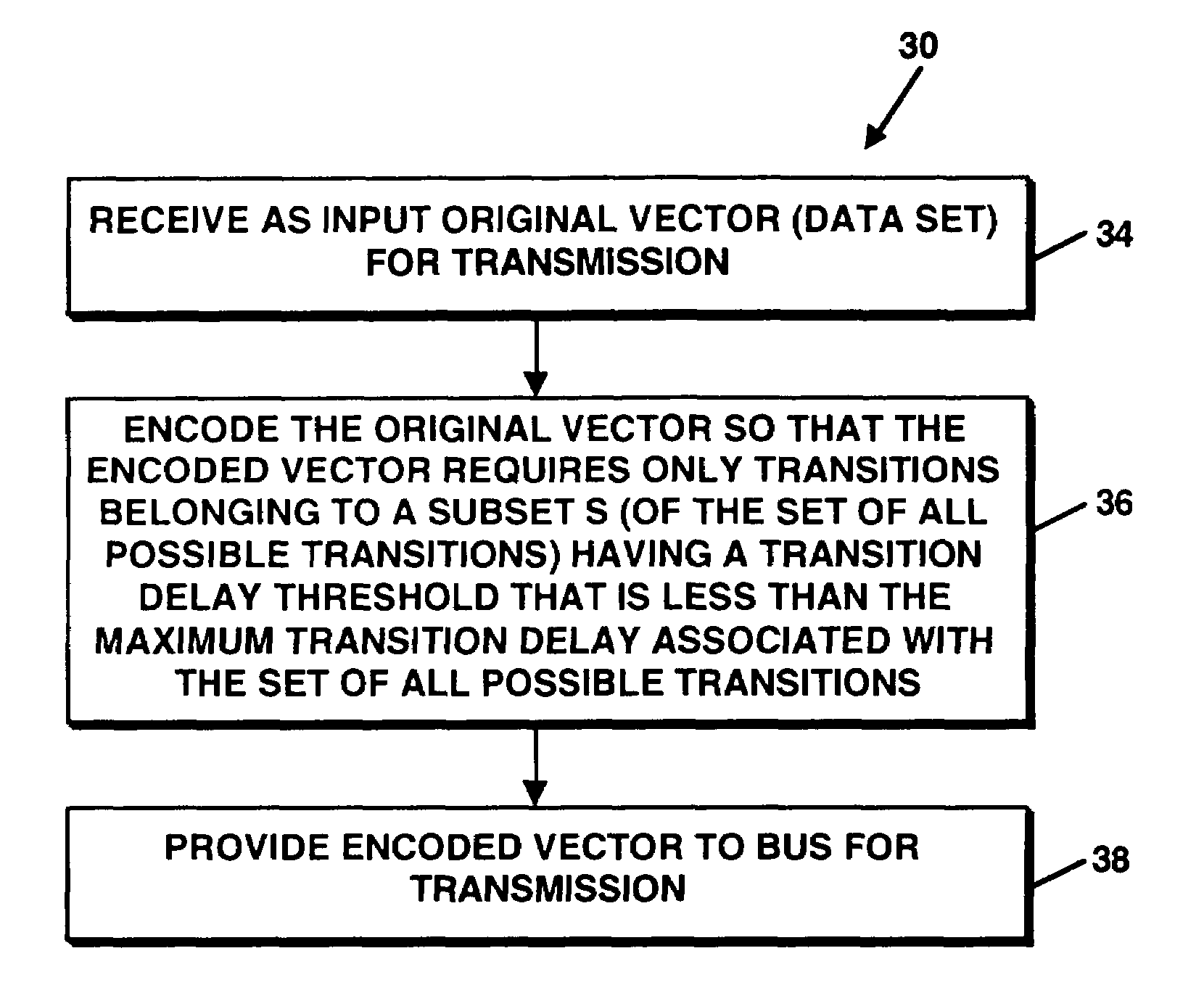
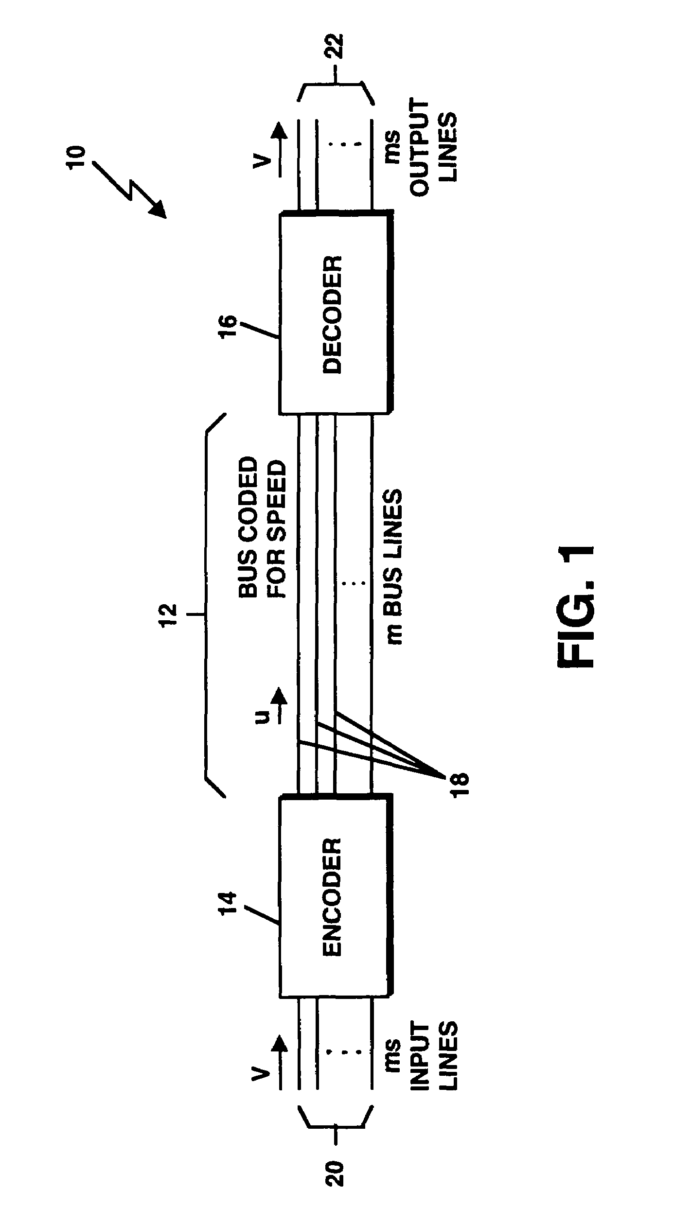
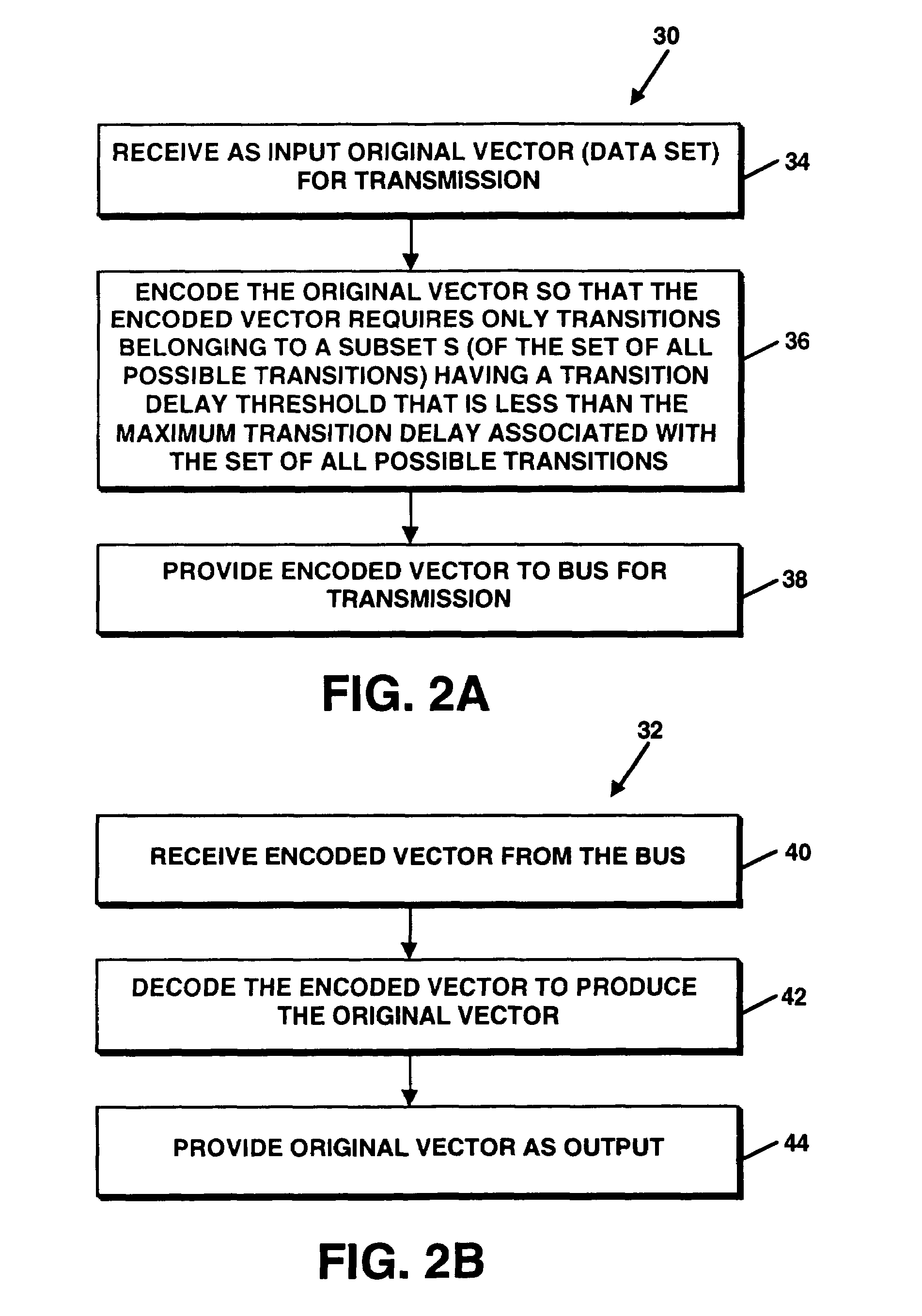
[0021]Referring to FIG. 1, an interconnect system or circuit 10 includes a bus 12 that is coupled to an encoder 14 at one end and a decoder 16 at the other end. The bus 12 includes “m” capacitively-coupled parallel bus lines 18. According to the invention, the bus 12 is “coded for speed”. Coding for speed on the bus 12 recognizes that coupling between the lines causes different transitions to require different amounts of time to complete. The encoder 14 receives input data intended for transmission on the bus over input lines 20 and encodes the data for transmission on the bus. The decoder 16 decodes the transmitted data and provides the decoded data at output lines 22. The encoder 14 and decoder 16 are configured to operate according to a coding scheme in such a way as to allow only certain, faster transitions to take place on the bus 12, thus increasing the clock frequency of the bus 12. The combinatorial capacity of such a constrained bus is the theoretical maximum rate that data...


PUM


Abstract

A mechanism for use with a bus provided from parallel, capacitively-coupled bus lines to restrict a number of possible transitions on the bus to a number that is smaller than the maximum number of possible transitions so that data transmissions on the bus occur at a transmission rate which is higher than the transmission rate allowable if the number of transitions had not been restricted.

Description

CROSS REFERENCE TO RELATED APPLICATIONS[0001]This application claims the benefit of U.S. Provisional Patent Application No. 60 / 352,632, filed Jan. 28, 2002, which is incorporated herein by reference in its entirety for all purposes.STATEMENT REGARDING FEDERALLY SPONSORED RESEARCH[0002]Not Applicable.FIELD OF THE INVENTION[0003]The present invention relates generally to transmission of data through buses.BACKGROUND OF THE INVENTION[0004]On-chip and inter-chip communications are realized by circuit devices called buses. A bus consists of parallel, aligned, similar wires that in most cases are on the same metal layer. Buses transmit units of information at a given fixed rate R (e.g., byte / sec). Some parallel buses are provided from parallel, capacitively-coupled transmission lines. The capacitive coupling introduces delay in the propagation of a signal from bus driver to bus receiver. Buses with capacitively-coupled lines have the property that the propagation time required for a signa...

Claims


Application Information

Patent Timeline
IPC IPC(8): H03M7/00
CPCH03M5/145H03M5/14
Inventor SOTIRIADIS, PAUL P.CHANDRAKASAN, ANANTHA
Owner MASSACHUSETTS INST OF TECH
Why Eureka
Try Eureka