WDM system having chromatic dispersion precompensation

a chromatic dispersion and precompensation technology, applied in the field of chromatic dispersion precompensation systems, can solve the problems of chromatic dispersion of 40 gbit/second cs-rz signals, degrade receiver sensitivity, and relatively high bit error rates

Active Publication Date: 2008-07-15
CIENA
View PDF35 Cites 23 Cited by
  • Summary
  • Abstract
  • Description
  • Claims
  • Application Information

AI Technical Summary

Problems solved by technology

40 Gbit / second CS-RZ signals, however, are susceptible to chromatic dispersion, a non-linear effect in which spectral components of an optical signal propagate through the optical fiber at different speeds with higher frequency components traveling slower than lower frequency components.
Chromatic dispersion can result in spectral components of one pulse arriving at a receiver at substantially the same time as a succeeding pulse, thereby causing degraded receiver sensitivity and a relatively high bit error rate.

Method used


Image

  • WDM system having chromatic dispersion precompensation
  • WDM system having chromatic dispersion precompensation
  • WDM system having chromatic dispersion precompensation

Examples


Embodiment Construction

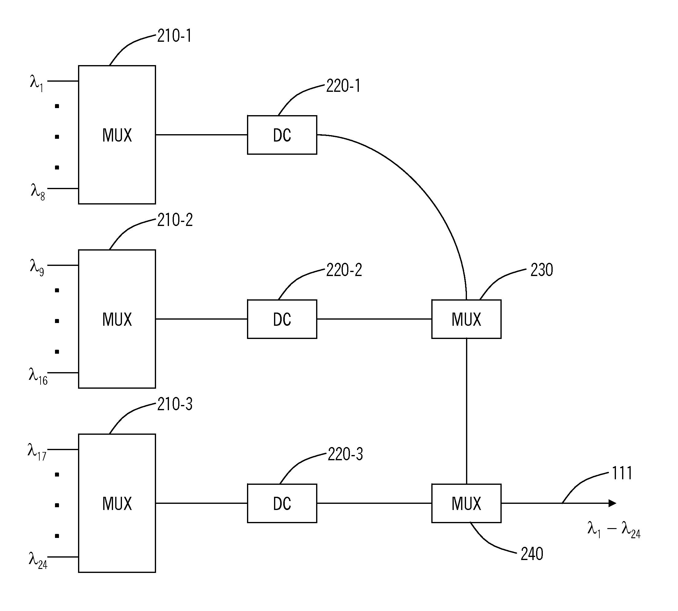
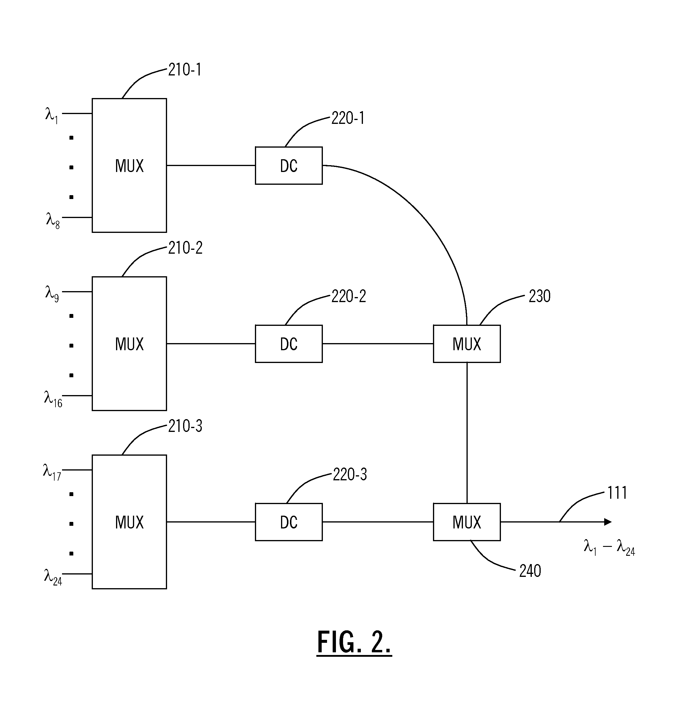
[0014]Chromatic dispersion in a high speed CS-RZ WDM transmission system is reduced by providing tailored “precompensation” for individual and / or groups of optical signals. Such precompensation is achieved by passing the optical signals through a dispersion compensating fiber or other dispersion compensating element prior to multiplexing the signals onto a single optical fiber. Additional dispersion compensation can be performed in optical amplifiers and within an optical demultiplexer downstream from the optical multiplexer.

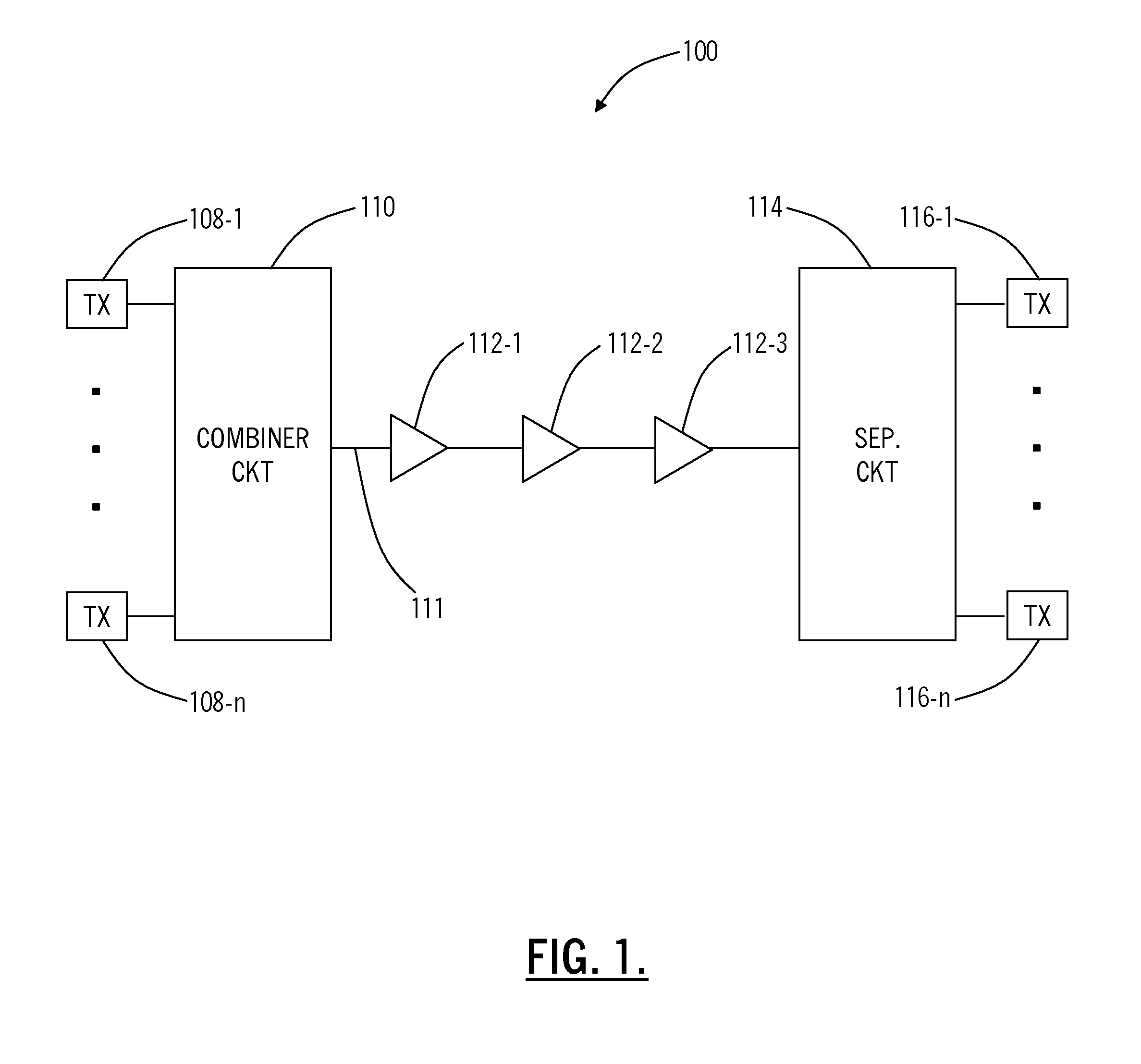
[0015]FIG. 1 illustrates WDM system 100 consistent with an aspect of the present invention. WDM system 100 includes an optical combiner circuit 110, which receives a plurality of optical signals from transmitters 108-1 to 108-n, and combines the optical signals onto an optical communication path 111. The optical signals often carry data at rates of 40 Gbits / second conforming to SDH STM-256 and / or SONET OC-768 protocols. The optical signals next pass through a pl...


PUM


Abstract

Chromatic dispersion in a high speed CS-RZ WDM transmission system is reduced by providing tailored “precompensation” for individual and / or groups of optical signals. Such precompensation is achieved by passing the optical signals through a dispersion compensating elements, such as dispersion compensating fiber, within an optical multiplexer, i.e., prior to multiplexing the signals onto a single optical fiber. Additional dispersion compensation can be performed in optical amplifiers and within an optical demultiplexer downstream from the optical multiplexer.

Description

[0001]The present invention is directed toward high data rate wavelength division multiplexed (WDM) optical communication systems.BACKGROUND OF THE INVENTION[0002]Wavelength division multiplexing (WDM) has been explored as an approach for increasing the capacity of fiber optic networks. In a WDM system, plural optical signals or channels are carried over a single optical fiber with each channel being assigned a particular wavelength. Such systems typically include a demultiplexer for separating and supplying the optical channels to corresponding optical receivers.[0003]In order to increase system capacity further, data rates associated with each optical signal have increased. In particular, data rates have increased from 2.5 Gbits / second to 10 Gbits / second in commercially available systems, and 40 Gbits / second per channel systems are currently in development.[0004]At relatively high data rates, such as 40 Gbits / second, different modulation formats have been considered for providing ...

Claims


Application Information

Patent Timeline
Patent Type & Authority Patents(United States)
IPC IPC(8): H04B10/12H04B10/00H04B10/18H04J14/02
CPCH04B10/2525H04J14/02H04B2210/254
Inventor SARDESAI, HARSHADTAYLOR, MICHAELUPADHYAY, SANJAYKUMAR
Owner CIENA
Why Eureka
Try Eureka