Variable dispersion compensator

a compensator and variable technology, applied in multiplex communication, instruments, optical elements, etc., can solve the problems of reducing the number of optical fibers, and increasing the fiber accommodation space required, so as to achieve a wide wavelength band and low group-delay ripple

Inactive Publication Date: 2007-06-28
HITACHI METALS LTD
View PDF6 Cites 8 Cited by
  • Summary
  • Abstract
  • Description
  • Claims
  • Application Information

AI Technical Summary

Benefits of technology

[0020] The present invention makes it possible to provide a variable dispersion compensator that has characteristics of a large amount of dispersion, a wide wavelength band, and a low grou

Problems solved by technology

The above-described conventional dispersion compensators, however, pose various problems.
This increases the fiber accommodation space required.
Additionally, since the dispersion compensation fiber is generally small in mode field diameter, the fiber may produce a significant nonlinear effect in the fiber and thus distort transmission waveforms.
It is therefore known that the optical fiber gratings are inferior to dispersion compensation fibers in transmission characteristics when used for dispersion compensation.
Also, there are manufacturing related problems in that optical fiber gratings for a large amount of dispersion or a wide wavelength band cannot be easily produced and in that optical fiber gratings for a narrow wavelength band require stability in tempe

Method used


Image

  • Variable dispersion compensator
  • Variable dispersion compensator
  • Variable dispersion compensator

Examples


Embodiment Construction

[0055] Embodiments of the present invention will be described in detail hereunder with reference to the accompanying drawings.

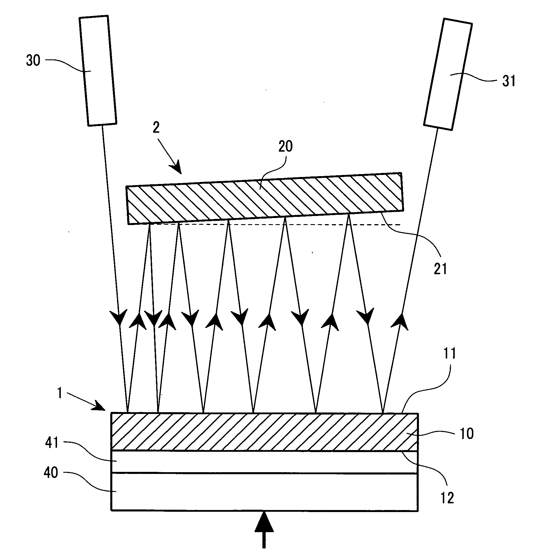
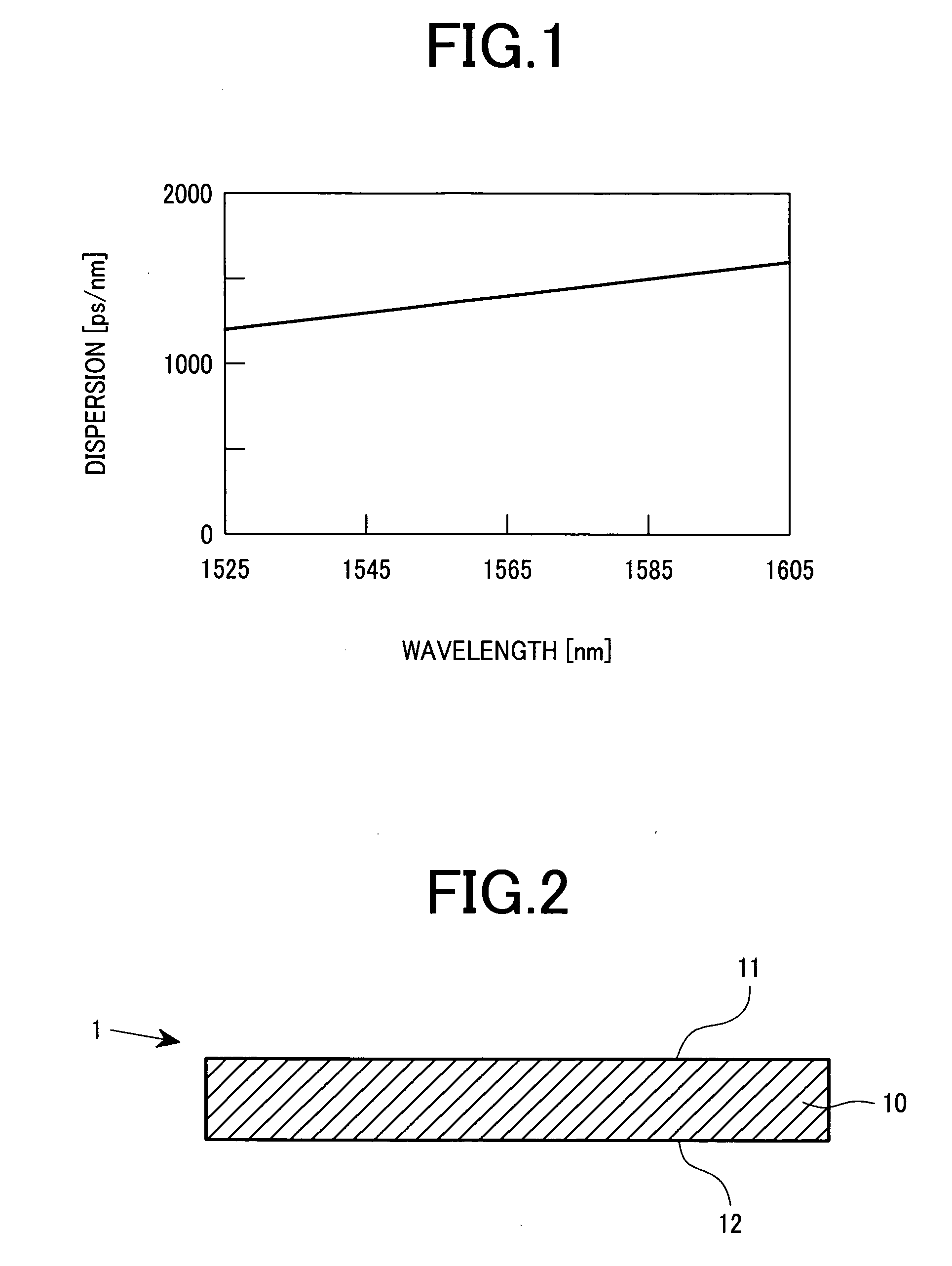
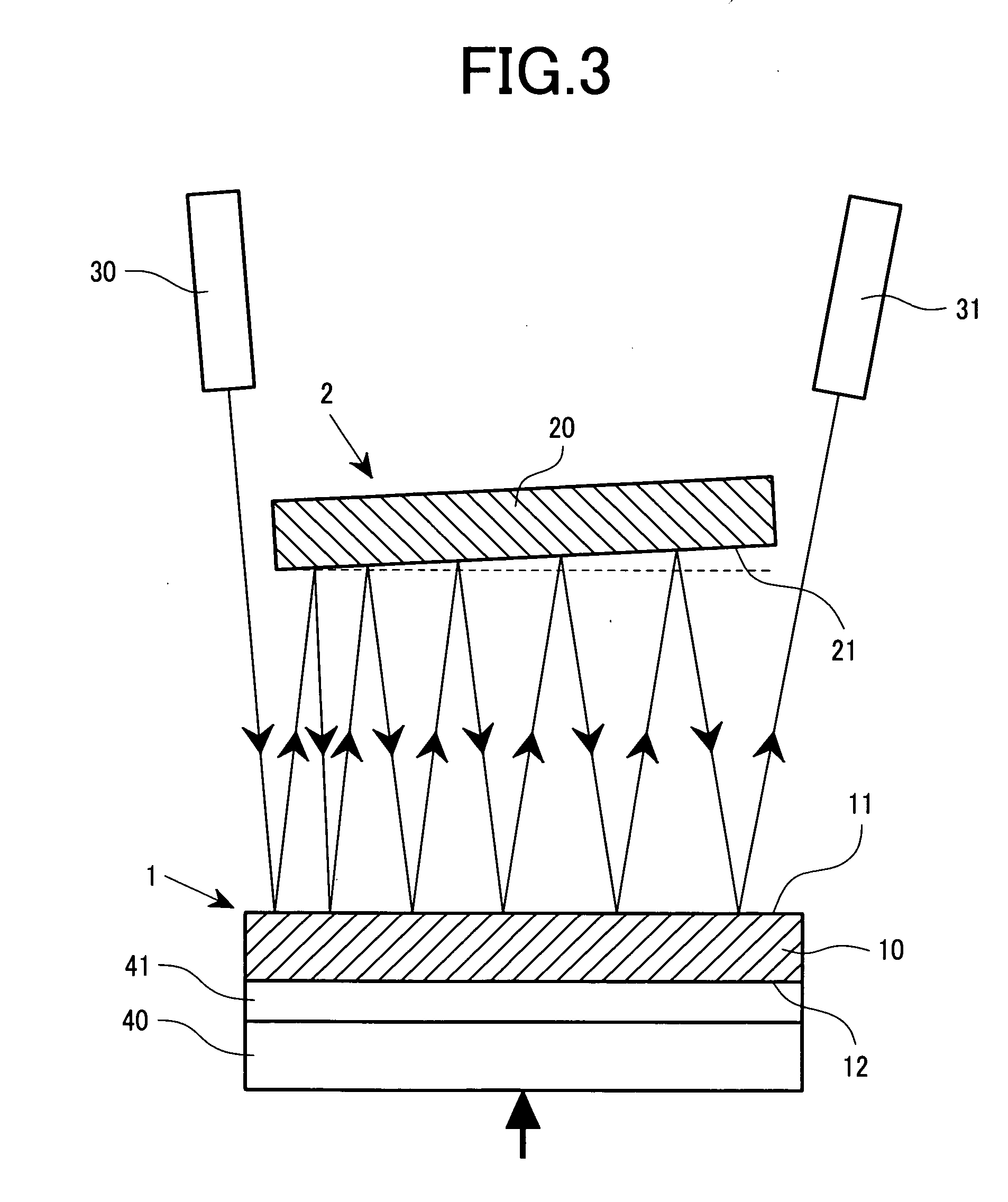
[0056] First, a description will be made of an etalon. FIG. 2 shows a cross-sectional structure of the etalon. Reference number 1 denotes the etalon. The etalon includes a planar plate 10 whose upper and lower surfaces are precisely parallel to each other and have reflection films 11 and 12 coated thereon. The reflection films may uses metal films made of a high-reflectance metallic material such as gold and silver, a dielectric multi-layer film, or the like. In particular, ideally, an etalon has an amplitude reflectance of 100% on its one surface. Such an etalon is called the GT etalon, which was named after Gires and Tournois, the proposers. In fact, however, it is difficult to obtain an amplitude reflectance of 100%. Thus, the reflection films may be allowed to have an amplitude reflectance of at least about 90%.

[0057] In addition, the amplitude reflecta...


PUM


Abstract

The present invention provides: (1) a compensator that compensates a wide range of amount of dispersion of light in a wide bandwidth band; and (2) a variable dispersion slope compensator applicable to the case where a transmission path suitable for a wavelength division multiplexing transmission system produces a wavelength dispersion slope. The present invention realizes: (1) a variable dispersion compensator that compensates a wide range of amount of dispersion of light in a wide bandwidth band; and (2) a variable dispersion slope compensator suitable for a wavelength division multiplexing transmission system. To realize the above, a dispersion compensating unit is provided with a structure in which a mirror is disposed in parallel to or with a slight angle relative to an etalon to reflect a light beam emitted from a collimator on the etalon multiple times and then emit the light beam into another collimator.

Description

CLAIM OF PRIORITY [0001] The present application claims priority from Japanese application JP 2005-371937, filed on Dec. 26, 2005, the content of which is hereby incorporated by reference into this application. BACKGROUND OF THE INVENTION [0002] 1. Field of the Invention [0003] The present invention relates to variable dispersion compensators, and more particularly, to an optical dispersion compensator suitable for application to optical transmission systems using optical fibers, and systems using an optical transmission scheme based on wavelength division multiplexing. [0004] 2. Description of the Related Art [0005] In resent years, research and development have been conducted on long-distance optical transmission systems that use optical amplifiers as repeaters. It is considered to be particularly effective to increase a capacity using wavelength division multiplexing (WDM) technique. The WDM technique multiplexes a plurality of optical signals with different wavelengths over a si...

Claims


Application Information

Patent Timeline
IPC IPC(8): H04J14/02G02B5/28G02B6/00G02B26/00G02B27/00H04B10/25H04B10/2507H04B10/2513H04B10/40H04B10/50H04B10/60
CPCG02B6/29358G02B6/29364G02B6/29394G02B6/29395G02B6/29398
Inventor SUGAWARA, TOSHIKIHOSOMI, KAZUHIKOMAKIO, SATOSHI
Owner HITACHI METALS LTD
Why Eureka
Try Eureka