
Manufacturing methods of double-spiral arc tubes

a technology of arc tubes and manufacturing methods, which is applied in the manufacture of electrode systems, electric discharge tubes/lamps, glass tempering apparatuses, etc., can solve the problems of double spiral deformation and frequent deformation, and achieve the effect of preventing the diameter of glass tubes, and facilitating and accurately managing the temperature of glass tubes

Inactive Publication Date: 2008-07-22
PANASONIC CORP
View PDF5 Cites 1 Cited by
  • Summary
  • Abstract
  • Description
  • Claims
  • Application Information

AI Technical Summary

Benefits of technology

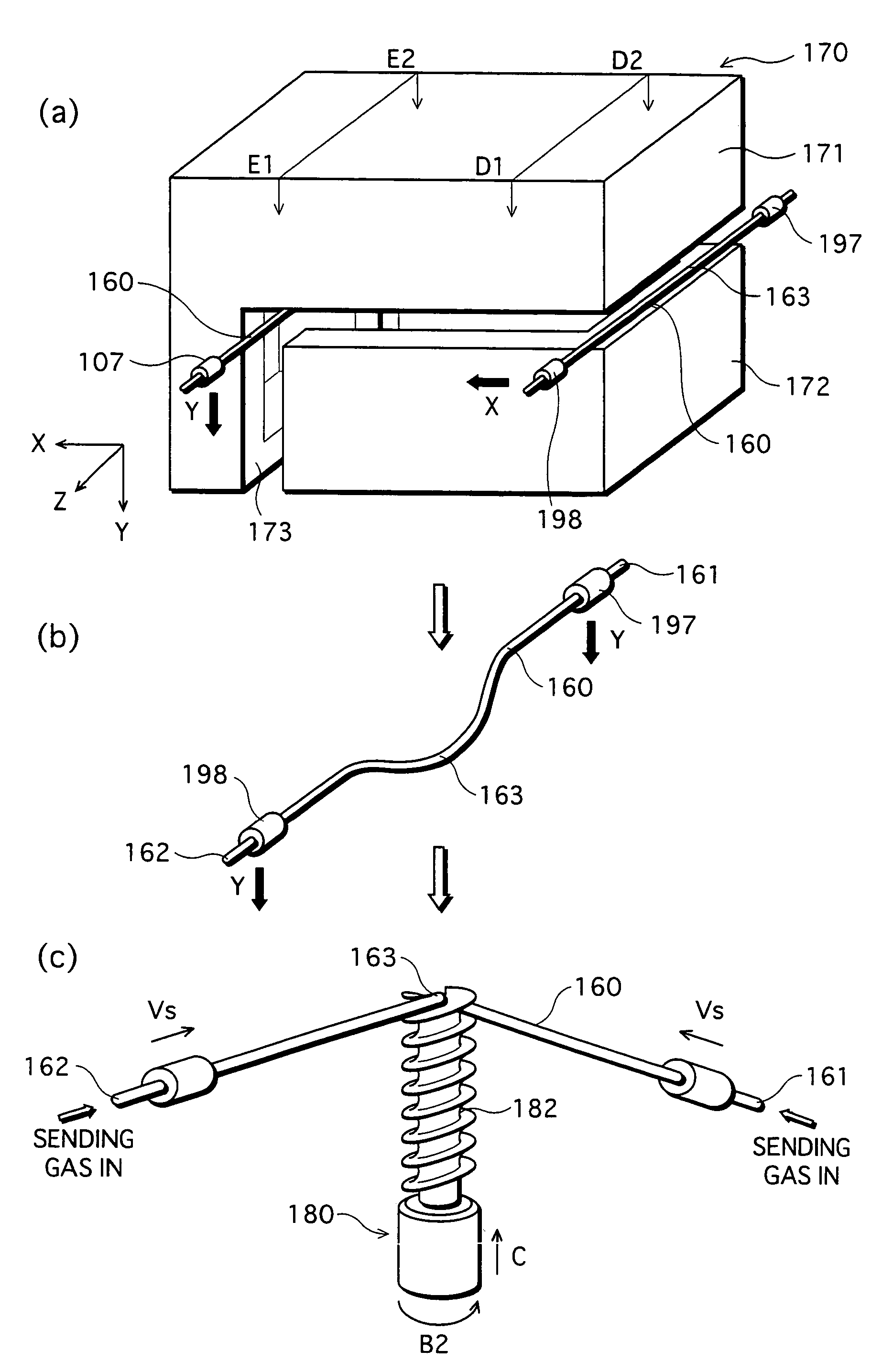
"The present invention provides a manufacturing method of a double-spiral arc tube that reduces defective products. The method involves hanging a softened glass tube with a mandrel and winding the tube along winding grooves on the mandrel. The mandrel is positioned beneath the glass tube and the tube is perpendicularly lowered and held on the mandrel. The glass tube can be shaped like a straight tube or an arc. The method ensures that the central portion of the glass tube sags in the same direction as the direction in which it is moved, making it easy to position the central portion with the mandrel and start winding the glass tube. The method also prevents the diameter of the glass tube from being too large or too small and ensures constant tension load on the glass tube during the winding process."

Problems solved by technology

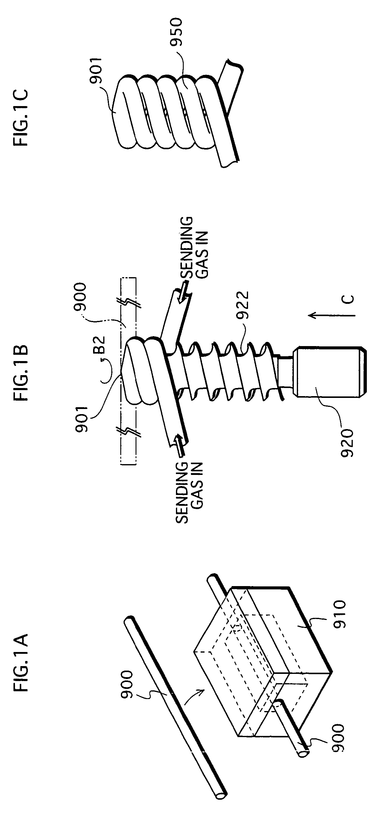
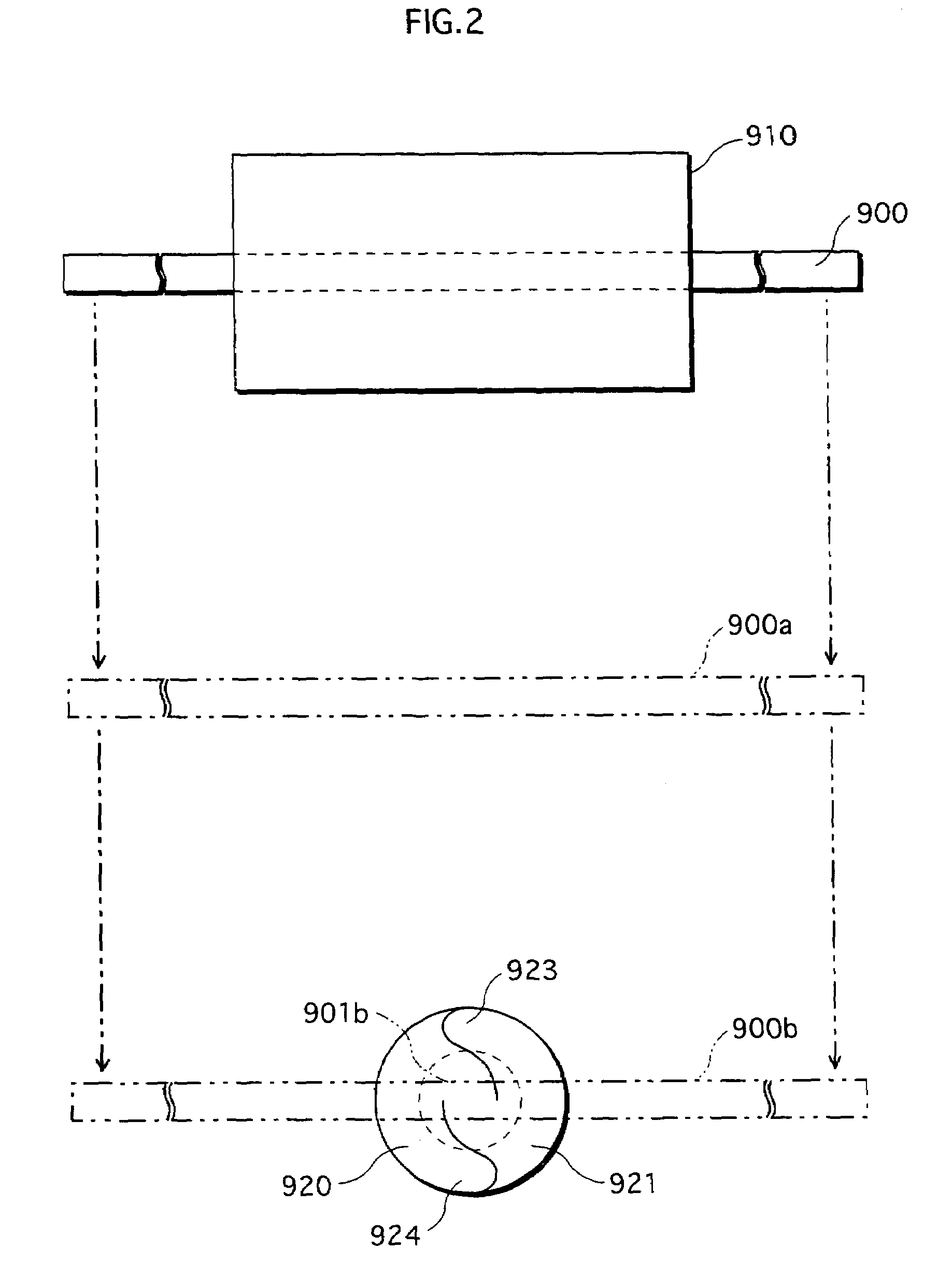
According to a conventional manufacturing method, however, there have been products with defects frequently because, for example, the glass tube 900 has not properly been wound along the winding grooves 922 of the mandrel 920, or even if the glass tube 900 has been properly wound, the double spiral happens to be deformed.

Method used


Image

  • Manufacturing methods of double-spiral arc tubes
  • Manufacturing methods of double-spiral arc tubes
  • Manufacturing methods of double-spiral arc tubes

Examples


Embodiment Construction

[0052]The following explains an embodiment in which the present invention is applied to an arc tube in a compact self-ballasted fluorescent lamp, with reference to the drawings FIGS. 5 through 14.

1. Structure

(1) Overall Structure

[0053]As shown in FIG. 5, the compact self-ballasted fluorescent lamp 100 comprises an arc tube 110, which is formed by bending a glass tube 120 into a double spiral; a holding member 210 in the shape of a bottomed cylinder for holding the arc tube 110; an electronic ballast 300 for turning on the light in the arc tube 110; a case 250 that is cone-shaped and fitted to the circumferential wall 220 of the holding member 210 so as to cover the electronic ballast 300; and a globe 400 that covers the arc tube 110. A base 380, which is the same type as one in an incandescent lamp, is attached to the lower side (the side that is opposite to the one into which the holding member 210 is fitted) of the case 250.

[0054]The electronic ballast 300 is structured with elect...


PUM

PropertyMeasurementUnit
softening pointaaaaaaaaaa
temperatureaaaaaaaaaa
diameteraaaaaaaaaa

Abstract

The manufacturing method comprises: a softening step of softening a straight glass tube in a heating furnace; a moving and placing step of moving the softened glass tube so that the glass tube is placed on the top of the mandrel; and a winding step of winding the glass tube placed on the top of the mandrel around the periphery of the mandrel. The mandrel is disposed beneath the glass tube starting to get soft, and the glass tube being soft is perpendicularly lowered in order to be placed on the top of the mandrel. In the winding step, the winding speed Vr at which the glass tube is wound around the mandrel is higher than the moving speed Vs at which chuck units holding the ends of the glass tube move toward the mandrel.

Description

[0001]This application is based on the applications No. 2003-105156 and No. 2004-73962 filed in Japan the content of which is hereby incorporated by reference.BACKGROUND OF THE INVENTION[0002]1. Field of the Invention[0003]The present invention relates to manufacturing methods of double-spiral arc tubes and to double-spiral arc tubes that are each formed by hanging and holding the substantially center of a softened glass on the top of a mandrel and winding the glass tube around the periphery of the mandrel.[0004]2. Description of the Related Art[0005]As an energy-saving era has started, low-pressure mercury discharge lamps that have high lamp efficiency and long lives, especially fluorescent lamps, have been attracting attentions. The inventors of the present invention have been studying the possibility of applying a glass tube bent into a double spiral to an arc tube used in such a fluorescent lamp. The advantageous effect of forming an arc tube into a double spiral is that this ki...

Claims


Application Information

Patent Timeline
Patent Type & Authority Patents(United States)
IPC IPC(8): C03B23/24C03B23/045C03B23/26C03B23/051C03B23/06H01J17/16H01J61/30H01J9/24H01J61/32
CPCC03B23/06H01J61/327H01J9/247Y02P40/57
Inventor YABUKI, TATSUHIROUCHIDA, NORIYUKIIWASAKI, TAKAYUKIIIDA, SHIRO
Owner PANASONIC CORP
Learn More