Method for monitoring a pipeline and position regulator for a control valve

a technology for controlling valves and pipelines, which is applied in the direction of valve operating devices, service pipe systems, water supply installation, etc., can solve the problems of sudden blockage of the flow through the pipeline, significant effort, and production outages and associated significant costs, so as to avoid operational faults or production outages, the effect of slow reduction of the free internal cross section of the pipelin

Inactive Publication Date: 2008-07-22
SIEMENS AG
View PDF18 Cites 8 Cited by
  • Summary
  • Abstract
  • Description
  • Claims
  • Application Information

AI Technical Summary

Benefits of technology

[0009]The advantage of the invention is that a pipeline can be monitored for slow blockage or accumulation solely using the means already available with control valves. Only the evaluation unit for the position value of the valve which is recorded by a position generator, which can be viewed as a component of the position regulator, has to be adapted in order to execute the method. Since such evaluation units are usually implemented by a processing unit with suitable software, this merely requires adaptation of the evaluation program to be processed by the processing unit in any event. The monitoring function can be easily deactivated if the requirements for monitoring are not available or not available at the time. Especially for an application of a control valve for checking for constant media flow through a pipeline an essentially constant throughflow of the medium for a major part of the operating time is required. By observing and evaluating the change of the lift position of the control valve over time a slow reduction of the free internal cross section of the pipeline is detected. If with an essentially constant throughflow of a medium the valve has to be opened further than a specifiable threshold, a signal to indicate the fact that the threshold has been exceeded is output. On the basis of this display signal suitable countermeasures can be taken at an early stage. For example the signal can be interpreted as an alerting signal for maintenance required, so that the pipeline can be cleaned or changed when maintenance is next performed on the process system. Operational faults or production outages can thus be avoided.
[0010]Preferably the first position of the control valve at the beginning of the operation of the process system, when the pipeline is still free of deposits, can be determined and stored. On regulation for constant throughflow this produces a degree of opening of the valve which can differ depending on the design of the plant.
[0011]Advantageously the method can be adapted to the relevant application by specifying the threshold value depending on the first position. The threshold value is set here in the range between full opening of the valve and the first position. The optimum position is again dependent on the relevant application, especially of the speed of depositing and the time intervals between the maintenance cycles. It has proved advantageous and suitable for many applications to output a display signal for a threshold value being exceeded, if the setting range remaining beyond the first setting to the opening of the valve is 80% used. This means that the signal is displayed at a point at which there is still a sufficiently safe interval before the onset of regulation problems, that is before regulation to a constant throughflow is no longer possible because the deposits in the pipeline are too large.
[0012]Since a long-term monotonously progressing deposit process is accompanied by a corresponding long-term monotonous shift in the position of the control valve, short duration peaks in the shift, which can be caused by pressure variations for example, can be suppressed by a lowpass filter, especially by forming a floating average, as regards their effect on the result of the diagnosis. This avoids a premature triggering of the pipeline monitoring and a premature output of a display signal for such fluctuations. Naturally other options can be applied for checking the plausibility of the relationship between the valve opening and material being deposited in the pipeline.
[0013]In addition or as an alternative to direct threshold comparison the change over time in the position of the control valve can be determined and the point in time estimated at which the position of the control valve is likely to exceed the specifiable threshold value. This has the advantage of allowing maintenance to be better planned, since not only the current blockage state of the pipeline, but also the speed of the reduction of the free internal cross section is taken into account.
[0014]To avoid a display signal being output prematurely for a threshold being exceeded It can be advantageous to determine the pressure of the medium in the pipeline and, if a permitted average value of the pressure is exceeded to interrupt the monitoring of the pipeline for blockage. The media pressure in the pipeline can for example be checked with a simple pressure switch at a feed point beyond a pump. Usually there are pressure converters in any event in process control systems, preferably at the ends of pipelines, for which the measured value can easily be included in the evaluation.

Problems solved by technology

Previously plant operators were somewhat surprised to find that the flow though a pipeline had been suddenly blocked by a blockage.
The mostly unexpected occurrence of a fault then causes production outages and the associated significant costs.
One possibility of detecting a reduction in the free pipeline cross section well in advance is an endoscopic investigation of the pipeline, but this can only be done by interrupting the process and thus entails significant effort.
The disadvantage of the method is that it is designed specifically for the requirements of an exhaust gas transport system and cannot simply be used as it is with other pipeline systems.
In addition no account is taken of the fact that on determination of the exhaust gas pressure for a fully open control valve on the basis of its characteristic curve, because of the increased volume stream the loss of pressure over the pipeline increases additionally.
The monitoring is thus comparatively imprecise.
In particular a leakage in a closed valve is audibly detected.

Method used


Image

  • Method for monitoring a pipeline and position regulator for a control valve
  • Method for monitoring a pipeline and position regulator for a control valve

Examples


Embodiment Construction

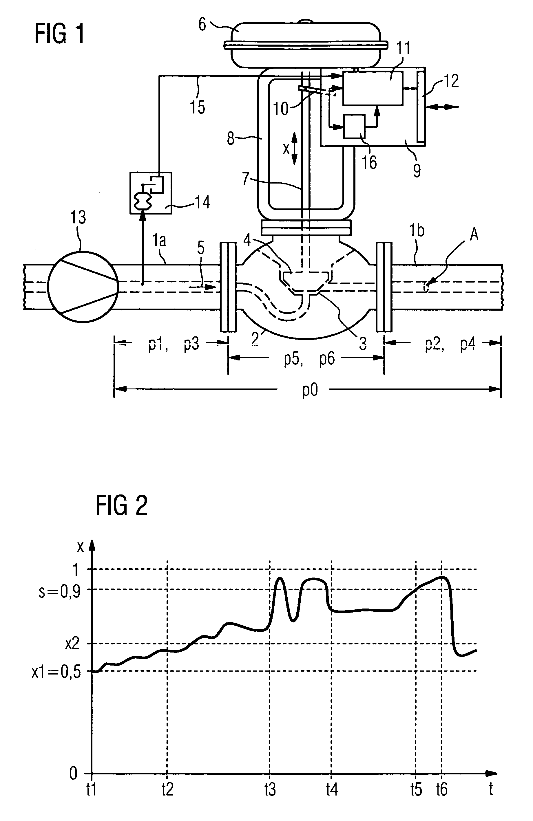
[0020]In accordance with FIG. 1, a valve 2 is built into a pipeline 1 with pipeline sections 1a and 1b of a process control system not shown in any greater detail, which by a corresponding lift of a closure element 4 operating in conjunction with a valve seat 3, controls the throughflow of a medium 5. The lift is generated by a pneumatic drive 6 transmitted by means of a valve stem 7 to the closure element 4. The drive 6 is connected via a yoke 8 to the housing of the valve 2. A position regulator 9 is arranged on the yoke 8. The relevant position x of the valve is recorded by a position generator 10 and fed to an evaluation unit 11, which compares it with required value fed in via a data interface 12 from a field bus with digital or analog data transmission and on the output side controls the pneumatic drive 6 in the sense of controlling the regulation difference. The required value is prespecified by a controller not shown in the Figure so that an essentially constant throughflow ...


PUM


Abstract

The invention relates to a method for monitoring a pipeline in order to detect the slow reduction of the free inner cross-section by means of the position of a control valve in the pipeline. When the flow rate is essentially constant, a first position is determined and stored at a first moment. According to at least one second position of the control valve, determined at a second, subsequent moment, the point at which the position of the valve exceeds a pre-deterrninable threshold value for a valve opening is determined, and optionally a signal is emitted to indicate that the threshold value has been exceeded and / or the time at which it was exceeded. As a result, suitable maintenance measures can be introduced, before faults occur in the process system.

Description

CROSS REFERENCE TO RELATED APPLICATIONS[0001]This application is the US National Stage of International Application No. PCT / DE2003 / 004096, filed Dec. 11, 2003 and claims the benefit thereof. The International Application claims the benefits of German application No. 10257910.5 filed Dec. 11, 2002, both applications are incorporated by reference herein in their entirety.FIELD OF THE INVENTION[0002]The invention relates to a method for monitoring a pipeline to detect a slow reduction in the free internal cross section with the aid of the position of a control valve in the pipeline, as well as to a position regulator for a control valve to execute the method.BACKGROUND OF THE INVENTION[0003]In many areas of process-control and energy technology the fault-free operation of a system depends on the pipelines, especially on their ability to let the relevant process medium pass through them. To avoid costly regular interruptions to operation it would be sensible to be able to detect well in...

Claims


Application Information

Patent Timeline
Patent Type & Authority Patents(United States)
IPC IPC(8): F16K37/00
CPCF16K37/0083F16K37/0091Y10T137/0318Y10T137/8242Y10T137/8175Y10T137/7761
Inventor HEER, KLAUS-PETER
Owner SIEMENS AG
Why Eureka
Try Eureka