Inlet nozzle for hot runner system

a technology of hot runner and inlet nozzle, which is applied in the direction of sweetmeats, dough shaping, food shaping, etc., can solve the problems of not having universal applications, many of the shut-off valves are not successful, and cannot be easily modified for different applications

Active Publication Date: 2008-07-29
INCOE CORP
View PDF6 Cites 3 Cited by
  • Summary
  • Abstract
  • Description
  • Claims
  • Application Information

AI Technical Summary

Benefits of technology

[0007]It is a further object of the present invention to provide a plastic injection molding system and process which maintains the internal pressure in the hot runner system and prevents ambient air from entering the system when the machine nozzle is retracted.
[0011]The present invention allows the internal pressure of the hot runner system to be retained and also prevents ambient air from entering the system which could cause inconsistencies in the molding process and lead to poor part quality.

Problems solved by technology

However, not all of the shut-off valves have been successful, and many do not have universal applications or are not able to be easily modified for different applications.

Method used


Image

  • Inlet nozzle for hot runner system
  • Inlet nozzle for hot runner system
  • Inlet nozzle for hot runner system

Examples


Embodiment Construction

)

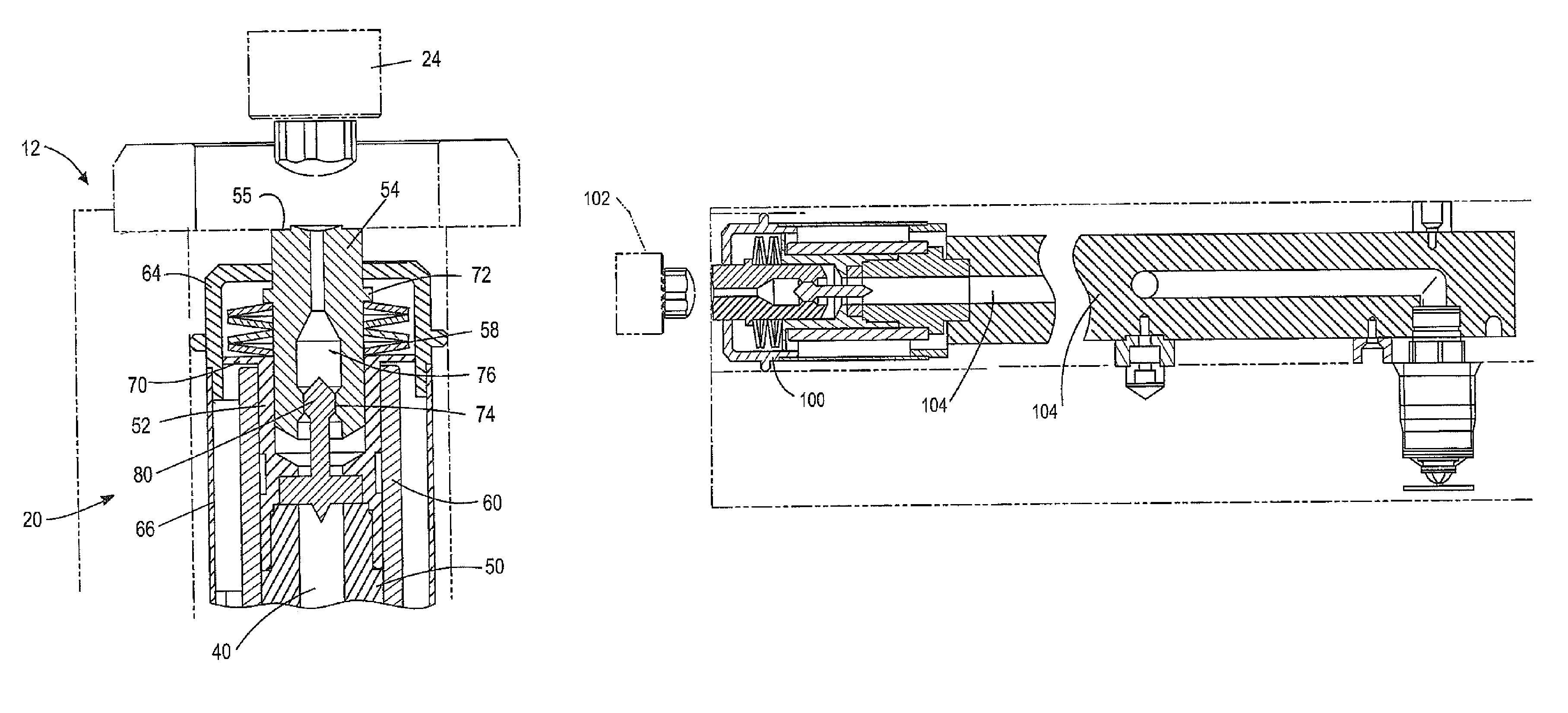
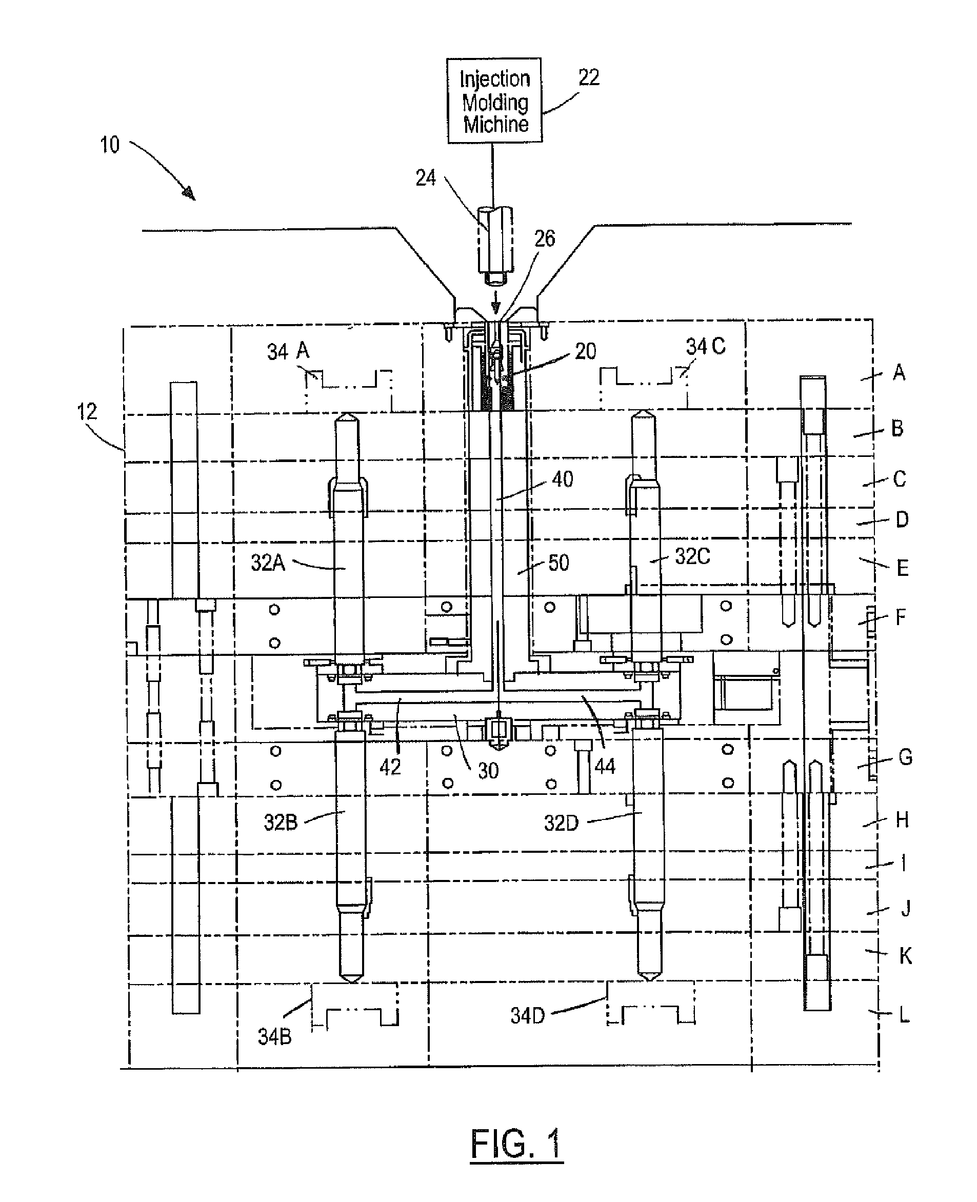
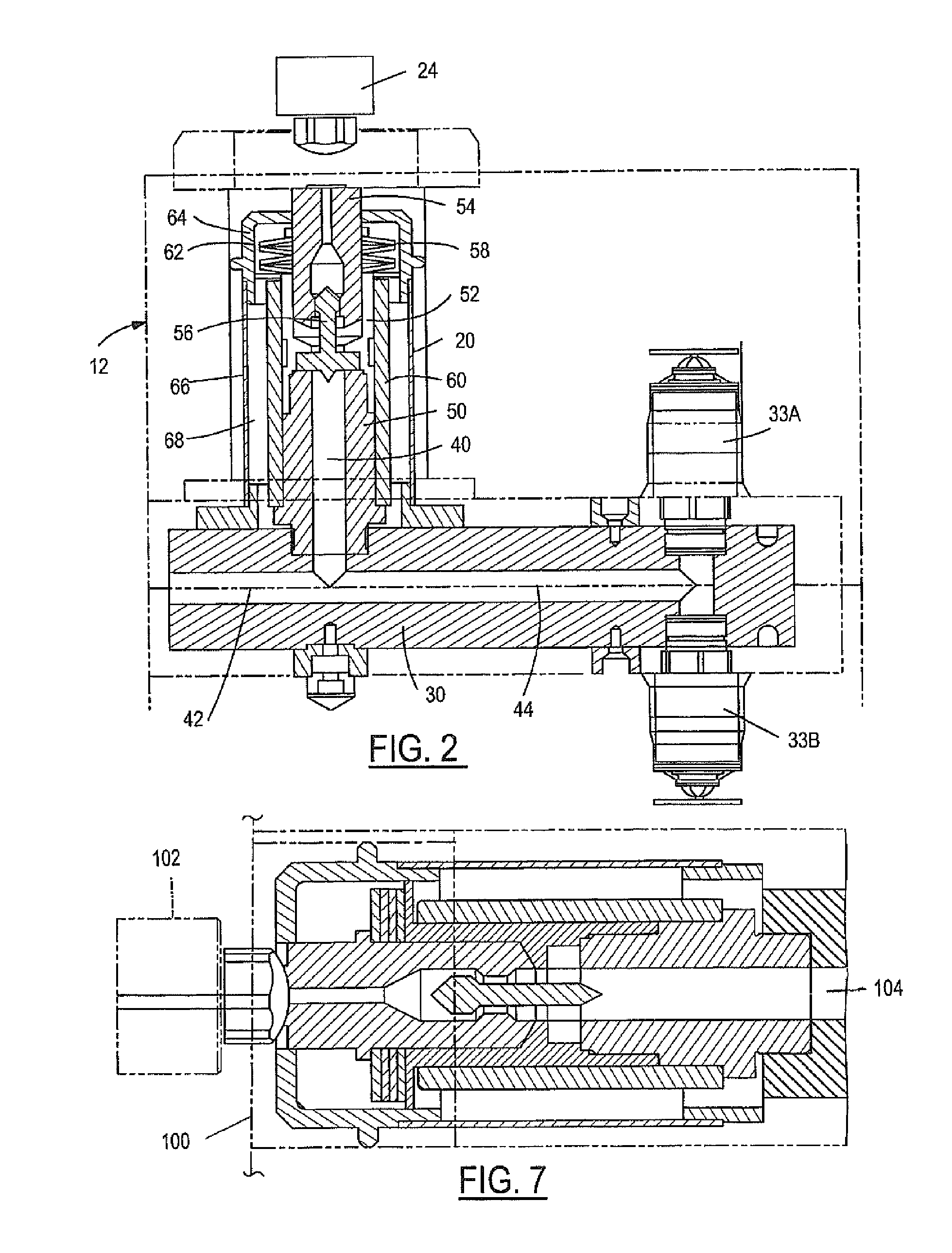
[0019]A preferred application for use of the present invention is shown in FIG. 1 and referred to generally by the reference numeral 10. The system 10 includes a stacked molding mechanism 12 which consists of a plurality of mold plates A-L. A shutoff valve mechanism 20 in accordance with the present invention is positioned between the stacked mold mechanism 12 and the injection molding machine 22. The injection molding machine has a machine nozzle 24 which is shown in FIG. 1, and is shown in its retracted position relative to the shutoff valve mechanism 20. The shutoff valve mechanism is preferably positioned in one of the layers of stacked molds or secured to an outer surface of the stacked mold mechanism. A hot runner manifold 30 is also positioned in the stack mold mechanism and plurality of sprue bushings 32 are attached to the hot runner manifold 30. The stacked mold mechanism 12 has a plurality of mold cavities 34 in which plastic molded products are produced.

[0020]When the i...


PUM

PropertyMeasurementUnit
axial lengthaaaaaaaaaa
temperatureaaaaaaaaaa
of timeaaaaaaaaaa

Abstract

A shutoff valve mechanism for a plastic injection molding system and process. The shutoff valve mechanism is positioned between the nozzle of the injection molding machine and the hot runner manifold. Force applied by the machine nozzle moves an inner body member in the shutoff valve mechanism and opens a valve allowing molten plastic material to flow through the valve and into the hot runner, sprue bushings, and mold cavities. A biasing mechanism, such as a plurality of spring washer members, returns the inner body member to its rest position, thereby closing the valve mechanism when the machine nozzle is retracted.

Description

TECHNICAL FIELD[0001]The present invention relates generally to plastic injection molding systems, and more particularly to shut-off valves between machine nozzles and hot runner manifolds.BACKGROUND OF THE INVENTION[0002]Plastic injection molding machines and systems are in common use today. The majority of plastic products and components that are in use today are made by plastic injection molding processes. In plastic injection molding systems, an injection molding machine melts plastic material and then injects the molten plastic material through a machine nozzle into a mold cavity. Typically, a hot runner manifold or system and a plurality of sprue bushings are positioned between the machine nozzle and the mold cavity. The hot runner manifolds distribute the molten plastic material from the machine nozzle through the sprue bushings and into multiple cavities in the mold or into different areas of a large cavity in a mold.[0003]In a typical injection molding process, the molten p...

Claims


Application Information

Patent Timeline
Patent Type & Authority Patents(United States)
IPC IPC(8): B29C45/00
CPCB29C45/1777B29C45/28B29C2045/207
Inventor GOINSKI, MICHAEL
Owner INCOE CORP
Why Eureka
Try Eureka