
Manufacturing method of nitride semiconductor device and nitride semiconductor device

a manufacturing method and technology of nitride semiconductor, applied in semiconductor devices, semiconductor lasers, semiconductor lasers, etc., can solve problems such as character degradation and yield reduction, and achieve excellent semiconductor characteristics and desirable product yields

Inactive Publication Date: 2008-07-29
EPISTAR CORP
View PDF24 Cites 2 Cited by
  • Summary
  • Abstract
  • Description
  • Claims
  • Application Information

AI Technical Summary

Benefits of technology

[0014]With the stated method, consistency of film thickness is maintained for the nitride semiconductor layers formed in the stacking step, which contributes to device characteristic enhancement and product yield improvement.
[0032]The stated structure enables constant film thickness for each nitride semiconductor layer constituting a nitride semiconductor device, and so enables manufacturing of a nitride semiconductor device having an excellent semiconductor characteristic as well as a desirable product yield.

Problems solved by technology

However, if crystal growth layers have inconsistent film thickness, etching in the waveguide forming process will be uneven, and so a resulting nitride semiconductor laser device will have problems such as characteristic deterioration and yield reduction.

Method used


Image

  • Manufacturing method of nitride semiconductor device and nitride semiconductor device
  • Manufacturing method of nitride semiconductor device and nitride semiconductor device
  • Manufacturing method of nitride semiconductor device and nitride semiconductor device

Examples


first embodiment

[0053]FIG. 3 is a sectional diagram drawn to explain film thickness of a layer structure formed on a GaN substrate in a nitride semiconductor device according to the first embodiment of the present invention.

[0054]In a nitride semiconductor device 101, a layer structure, which is made of a crystal growth layer 104 of a nitride semiconductor, is formed on a front surface 103 of a GaN substrate 102.

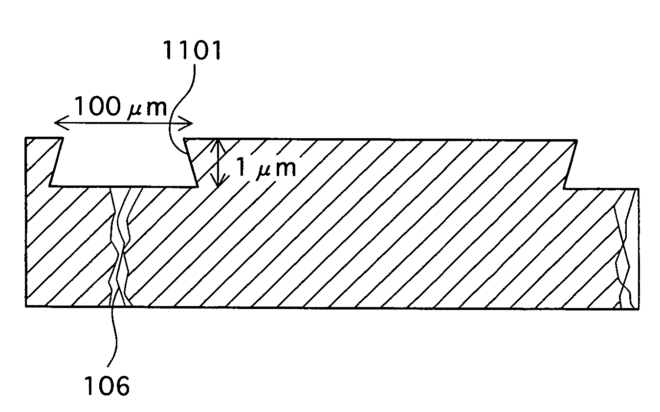
[0055]In the GaN substrate 102, dislocation concentrated regions 106 and 107 are formed. The dislocation concentrated regions 106 and 107 have concentrated therein defect crystals and align as stripes that pass through the GaN substrate 102 from the front surface 103 to a back surface 105. Moreover, grooves 108 and 109 are formed along a direction in which the dislocation concentrated regions 106 and 107 extend.

[0056]Then, crystal growth materials including group-III element and N element (e.g. Ga, Al, In) are supplied, using the MOCVD method, to the front surface 103 of the GaN substrate 1...


PUM

PropertyMeasurementUnit
widthaaaaaaaaaa
thicknessaaaaaaaaaa
distanceaaaaaaaaaa

Abstract

Provided is a manufacturing method of a nitride semiconductor device having a nitride semiconductor substrate (e.g. GaN substrate) in which dislocation concentrated regions align in stripe formation, the dislocation concentrated regions extending from a front surface to a back surface of the substrate, the manufacturing method being for stacking each of a plurality of nitride semiconductor layers on the front surface of the substrate in a constant film thickness. Grooves are formed on the nitride semiconductor substrate in the immediate areas of dislocation concentrated regions. Each of the nitride semiconductor layers is formed as a crystal growth layer on the main surface of the nitride semiconductor substrate to which the grooves have been formed.

Description

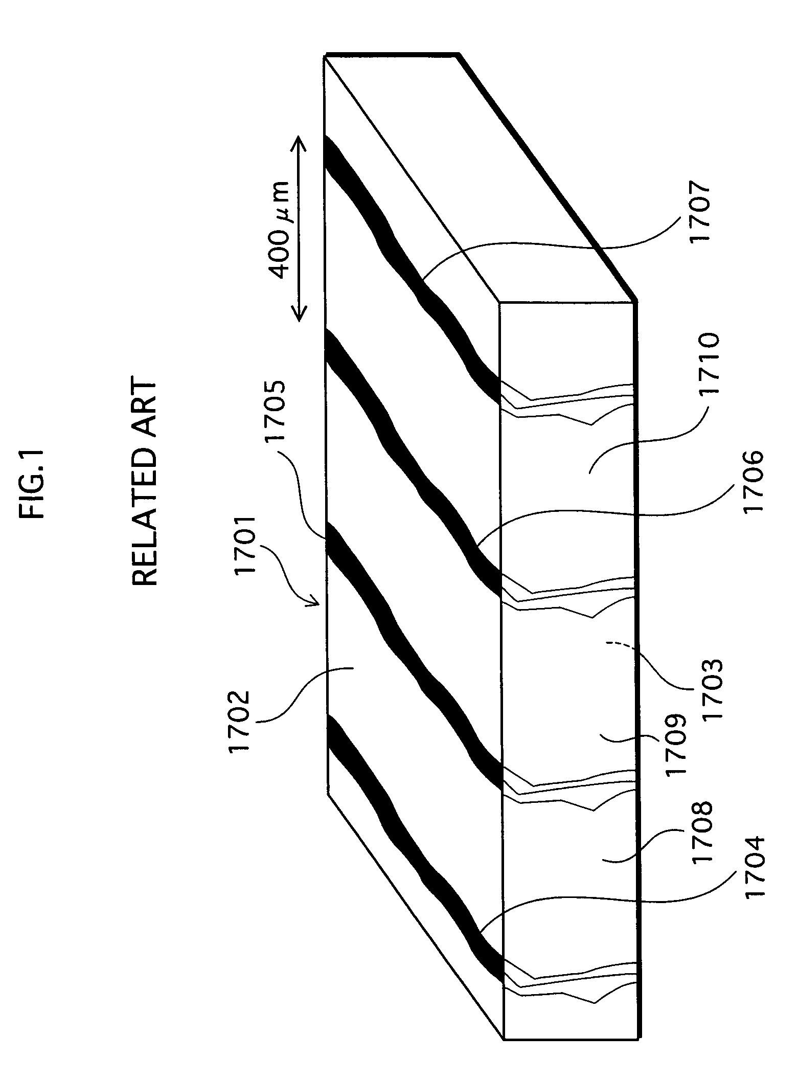
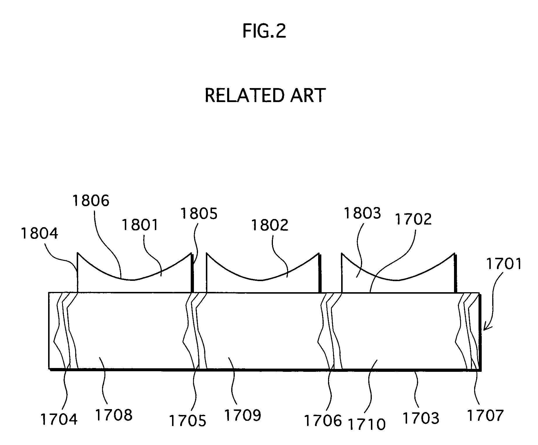
BACKGROUND OF THE INVENTION[0001](1) Field of the Invention[0002]The present invention relates to a manufacturing method of a nitride semiconductor device and to a nitride semiconductor device.[0003](2) Related Art[0004]Recently, many efforts are put into development relating to nitride semiconductor devices which are usable as a light source of next-generation optical disks of large capacity. One example is shown in International publication No. WO 03 / 038957A1.[0005]A nitride semiconductor device is manufactured by subjecting each of nitride semiconductor layers to crystal growth on a nitride semiconductor substrate, using a MOCVD (metal organic chemical vapor deposition) method.[0006]FIG. 1 is a perspective diagram schematically showing one example of such a nitride semiconductor substrate.[0007]A nitride semiconductor substrate 1701 is made of: dislocation concentrated regions 1704, 1705, 1706, and 1707 which have concentrated therein defect crystals and align as stripes that pas...

Claims


Application Information

Patent Timeline
Patent Type & Authority Patents(United States)
IPC IPC(8): H01L21/00H01L29/20H01L21/20H01L21/205H01L21/3065H01L21/76H01L33/32H01S5/00H01S5/223H01S5/343
CPCH01L21/02389H01L21/0243H01L21/02458H01L21/0262H01L21/02639H01L21/0254H01L33/025H01L33/0075
Inventor KANO, TAKASHIYAMAGUCHI, TSUTOMUIZU, HIROAKIHATA, MASAYUKINOMURA, YASUHIKO
Owner EPISTAR CORP
Learn More