Method for controlling variable damper in vehicle

a variable damper and vehicle technology, applied in the direction of cycle equipment, instruments, transportation and packaging, etc., can solve the problems of inability to realize the concept, the number of vehicles cannot be reduced when mass-producing vehicles, and the inability to place four sensors on a single plan

Active Publication Date: 2008-07-29
HL MANDO CORP
View PDF14 Cites 5 Cited by
  • Summary
  • Abstract
  • Description
  • Claims
  • Application Information

AI Technical Summary

Benefits of technology

[0013]Accordingly, the present invention is conceived to solve the aforementioned problems in the prior art. An object of the present invention is to provide a method of controlling a variable damper in a vehicle wherein a rear-wheel variable damper can be controlled by estimating a vertical acceleration value of a rear wheel based on the fact that there is a certain time delay in a wheel motion between front and rear wheels due to the wheelbase and vehicle speed.
[0014]According to an aspect of the present invention for achieving the object, there is provided a method of controlling a variable damper, which comprises the steps of (a) detecting vehicle body accelerations other than a desired vehicle body acceleration of a vehicle body; (b) calculating the desired vehicle body acceleration based on the other detected vehicle body accelerations according to a geometric rule; (c) calculating vehicle body vertical velocities by filtering the vehicle body accelerations to eliminate DC offsets therefrom and integrating the filtered accelerations; (d) detecting accelerations of front right / left vehicle wheels; (e) calculating front wheel vertical velocities by filtering the detected accelerations of the front right / left wheels to eliminate DC offsets therefrom and integrating the filtered accelerations, and then calculating accelerations of rear wheels by time delaying the accelerations of the front wheels by a time interval taken while a road input to the front wheel is delivered to the rear wheel at a vehicle speed; and (f) calculating damper velocities based on the calculated vehicle body vertical velocities and the calculated vehicle wheel vertical velocities.

Problems solved by technology

That is, the term ‘Sky-hook’ is used to illustrate the concept that a vehicle is mounted to a virtual sky over the vehicle by means of a damper having a fixed damping coefficient, but this concept cannot be actually implemented.
However, since the four, i.e. front / rear and left / right, G sensors installed at the vehicle wheel are subjected to an independent suspension mode and an independent motion, the four sensors cannot be positioned on a single plane.
As a result, since all the four sensors should be used to implement the Sky-hook control, the number of parts of vehicles cannot be reduced when mass-producing the vehicles.
Accordingly, there is a problem in that a cost for a finished vehicle will be increased and an unnecessary economical burden may thus be imposed on the consumer.

Method used


Image

  • Method for controlling variable damper in vehicle
  • Method for controlling variable damper in vehicle
  • Method for controlling variable damper in vehicle

Examples


Embodiment Construction

[0021]A plurality of preferred embodiments of the present invention may be presented. Hereinafter, a preferred embodiment of the present invention will be described in detail with reference to the accompanying drawings. Those skilled in the art will be able to easily understand the above and other objects, features and advantages of the present invention through the preferred embodiment of the present invention.

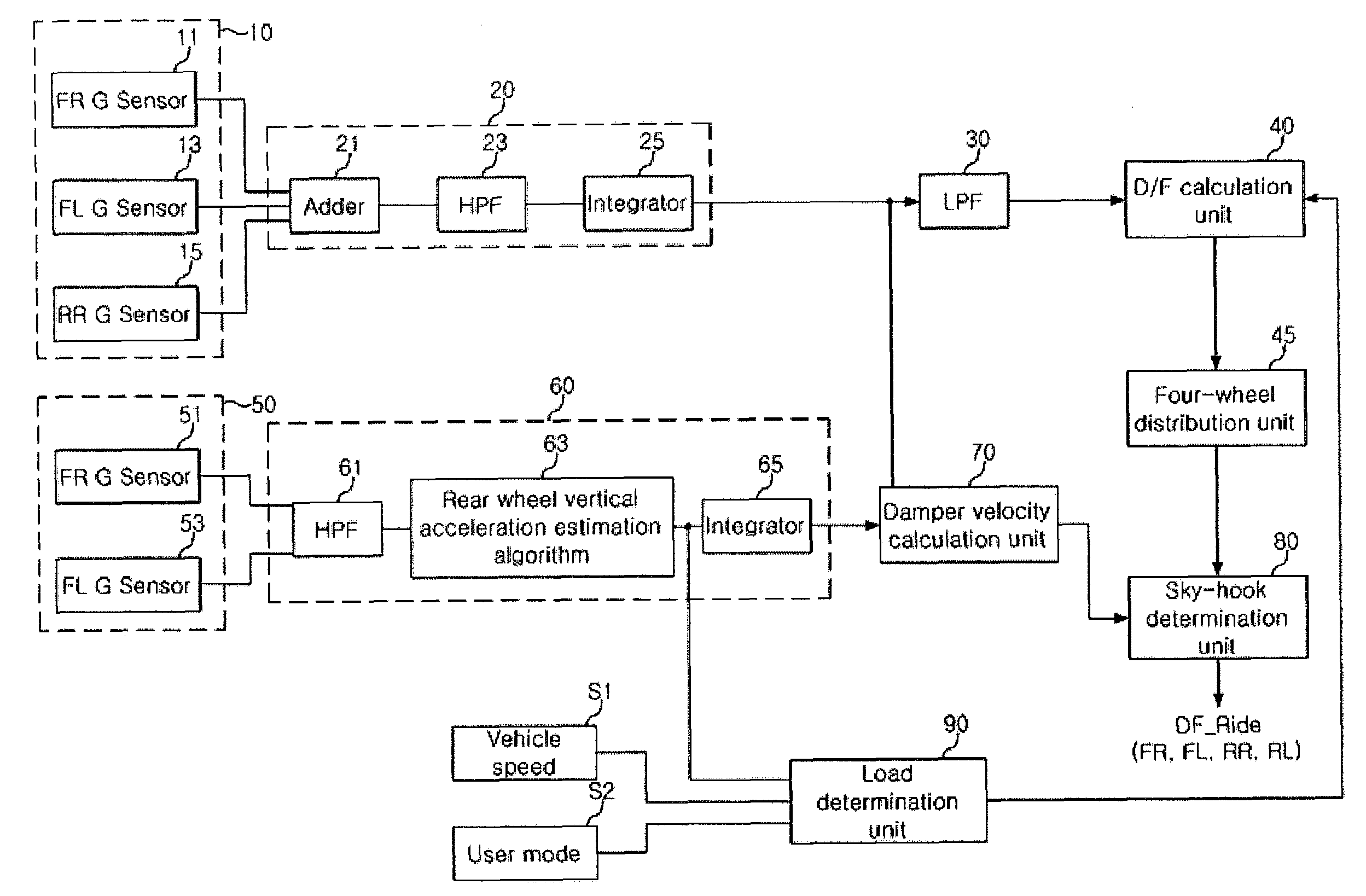
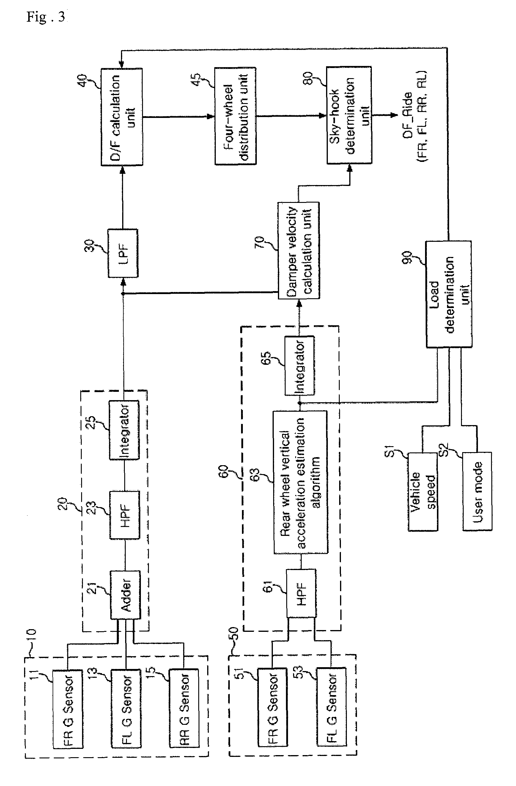
[0022]FIG. 3 is a block diagram illustrating a method of controlling a variable damper in a vehicle according to the present invention. Referring to FIG. 3, a system for controlling a variable damper according to the present invention comprises a vehicle body sensor unit 10, a vehicle body vertical velocity calculation unit 20, a low pass filter (LPF) 30, a D / F calculation unit 40, a four-wheel distribution unit 45, a vehicle wheel sensor unto 50, a vehicle wheel vertical velocity calculation unit 60, a damper velocity calculation unit 70, a Sky-hook determination unit 80, an...


PUM


Abstract

The present invention relates to a method of controlling a variable damper in a vehicle wherein a rear-wheel variable damper can be controlled by estimating a vertical acceleration value of a rear wheel based on the fact that there is a certain time delay in a wheel motion between front and rear wheels due to the wheelbase and vehicle speed. To this end, the method of the present invention comprises the steps of (a) detecting vehicle body accelerations other than a desired vehicle body acceleration of a vehicle body; (b) calculating the desired vehicle body acceleration based on the other detected vehicle body accelerations according to a geometric rule; (c) calculating vehicle body vertical velocities by filtering the vehicle body accelerations to eliminate DC offsets therefrom and integrating the filtered accelerations; (d) detecting accelerations of front right / left vehicle wheels; (e) calculating front wheel vertical velocities by filtering the detected accelerations of the front right / left wheels to eliminate DC offsets therefrom and integrating the filtered accelerations, and then calculating accelerations of rear wheels by time delaying the accelerations of the front wheels by a time interval taken while a road input to the front wheel is delivered to the rear wheel at a vehicle speed; and (f) calculating damper velocities based on the calculated vehicle body vertical velocities and the calculated vehicle wheel vertical velocities. Accordingly, the Sky-hook determination can be more accurately made. Further, since it is not necessary to use all the four sensors, the number of parts of vehicles can be reduced when mass-producing the vehicles. Consequently, the selling prices for finished vehicles can be lowered, and thus, an unnecessary economical burden cannot be imposed on the consumers.

Description

BACKGROUND OF THE INVENTION[0001]1. Field of Invention[0002]The present invention relates to a method for controlling a variable damper in a vehicle, and more particularly, to a method for controlling a continuously variable damper for a vehicle wherein only a front-wheel G sensor can be used to estimate a vertical acceleration value of a rear wheel in a state where a rear-wheel G sensor is removed.[0003]2. Description of the Prior Art[0004]In general, a vehicle suspension system is an important device for connecting a vehicle axle and body and absorbing vibration or shock exerted from a road surface to a vehicle axle to prevent the shock from being transferred directly to the vehicle body. This device provides the following three major functions.[0005]First, the vehicle suspension system provides a passenger with ride comfort by effectively eliminate an irregular input generated from a road surface while a vehicle is traveling. Second, an improved handling performance can be provid...

Claims


Application Information

Patent Timeline
Patent Type & Authority Patents(United States)
IPC IPC(8): B60G21/045B60G21/067B60G23/00G06F17/00
CPCB60G17/018B60G17/08B60G2400/202B60G2400/102B60G17/015
Inventor KIM, JONG HEONKIM, WAN IL
Owner HL MANDO CORP
Why Eureka
Try Eureka