Sensor arrangement

a technology of sensors and tyres, applied in the direction of electrical/magnetic measuring arrangements, tyre parts, tyre measurements, etc., can solve the problems of deterioration of the characteristics and functions of different structures, and achieve the effect of less expensive and larger tensions and effects

Inactive Publication Date: 2008-08-05
VASASENSOR
View PDF46 Cites 29 Cited by
  • Summary
  • Abstract
  • Description
  • Claims
  • Application Information

AI Technical Summary

Benefits of technology

[0017]Moreover, using sensors comprising a piezo-electric plastic or polymer material, according to one main aspect of the invention, gives certain advantages such as possibility for having larger detector elements. Moreover, the piezo-electric plastic material is less expensive than piezo-electric ceramic material. Furthermore, the piezo-electric plastic material can provide larger tensions and effects than the piezo-electric ceramic material as well. Yet, the two main advantages are the anisotropic characteristics of a piezo-elastic plastic material being utilized in the invention and the non-brittleness (plasticity).

Problems solved by technology

Moreover, the characteristics and functions of different structures are deteriorated in course of time.

Method used


Image

  • Sensor arrangement
  • Sensor arrangement
  • Sensor arrangement

Examples


second embodiment

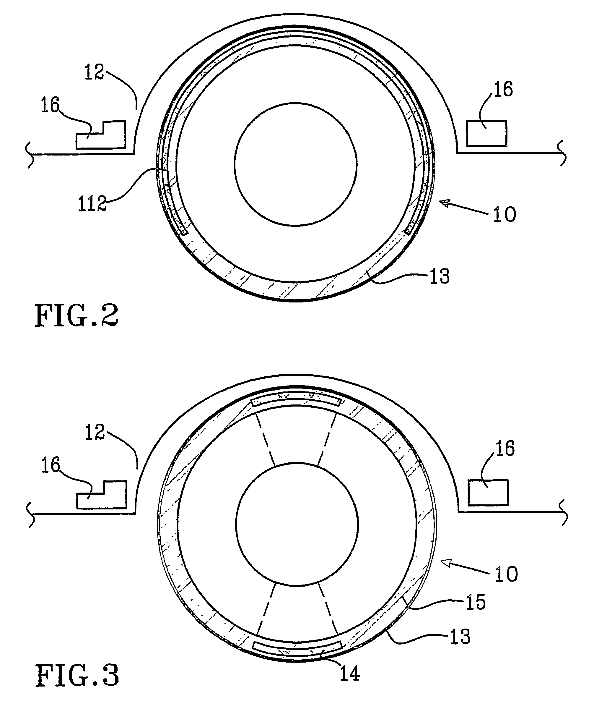
[0046]However, on the contrary, the sensor 112 in the second embodiment as shown in FIG. 2, elongates during the time the part of the tyre that contains the sensor has contact with the ground. During that time interval, an electric signal is created. The linear velocity of rotation can be obtained if the length of the strip is known simply by dividing this length by the duration of the voltage / current pulse.

[0047]Additional information is provided by the frequency at which the pulses occur due to the rotation of the vehicle. Both are related to each other and to the linear velocity of tyre motion. The difference in linear velocity of the tyre calculated from the pulse duration and from the frequency of tyre rotation (which is proportional to the angular speed of tyre rotation from which linear velocity of tyre motion can be calculated assuming certain tyre diameter, for example the diameter the tyre has at an appropriate air pressure) using appropriate software should be constant. W...

third embodiment

[0050]In the invention, the sensor 14 is arranged inside the tyre material, see FIG. 3. In this case, the sensor 14 is made of a magnetic material, which is dispersed and disintegrated in the material of the tyre 13, and preferably arranged, in a top layer of the tyre 13. The magnetic sensors 14 are arranged spaced apart (distance 15) inside the material of the tyre 13. As the tyre 13 wears out results are: (1) the amount of the magnetic material decreases, and (2) the distance between the tyre 13 and a preferred detector means, which detector means is to be explained in the following.

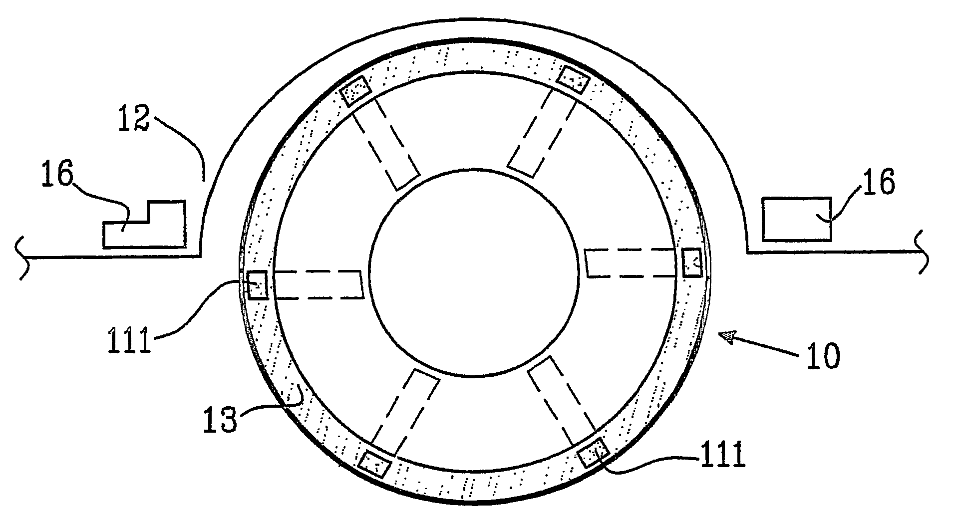
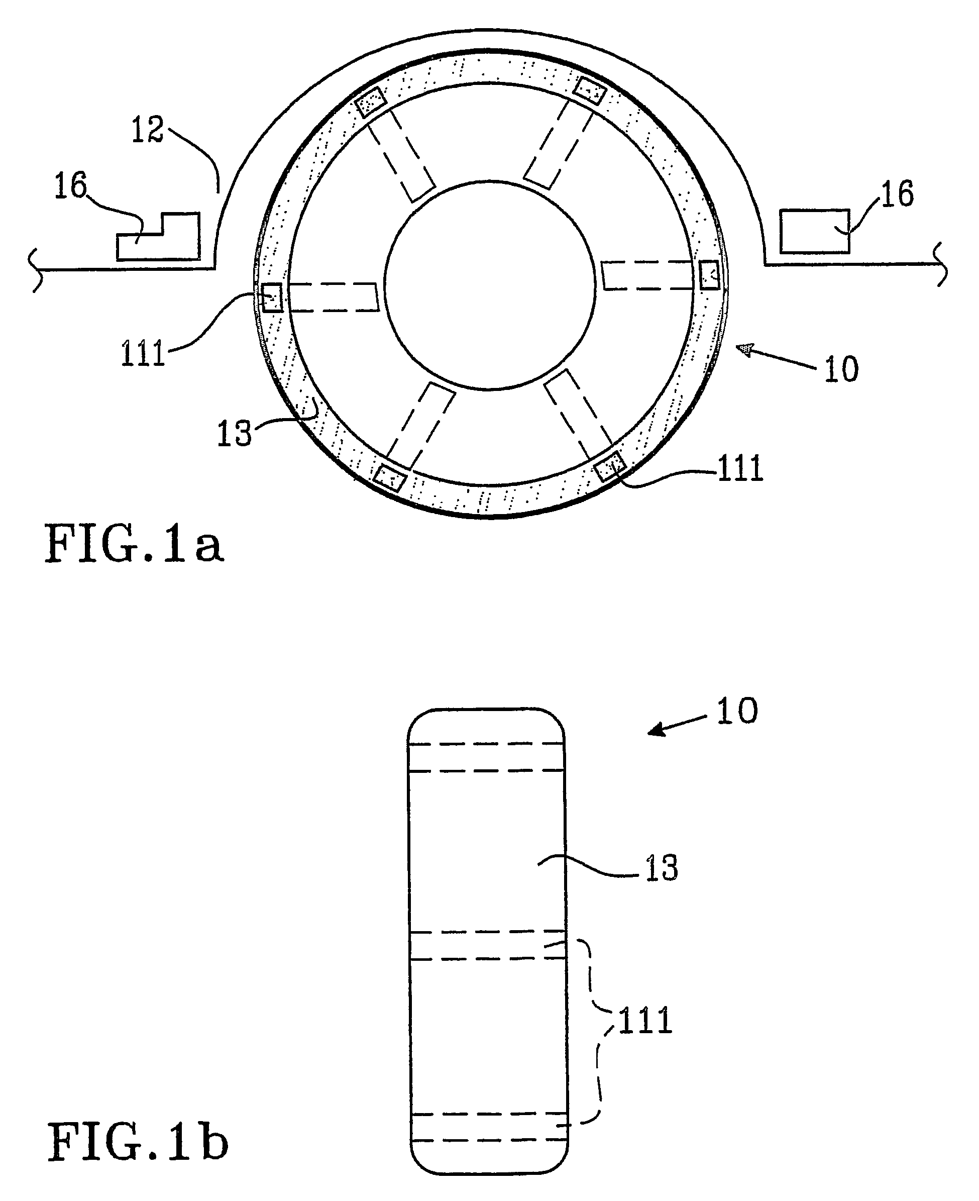
[0051]In all aforementioned embodiments, one or several detector means 16 for detecting the sensors 111, 112 and 14 (or a signal from the sensors) are arranged and generate a signal. Preferably, the detectors 16 are arranged inside a wheel housing in a conventional vehicle close to the tyre 13. Advantageously, two detectors 16 are arranged on each side of the tyre 13 to be measured, and at a specified ...

fifth embodiment

[0067]In a fifth embodiment, which is shown in FIG. 5a, two rolls 33 are preferably arranged in a printer application 20 for feeding paper sheets (or other information carrier). At least one sensor 331 is arranged on the surface of the printing paper, or substantially within the printer paper 32. In the preferred embodiment, the sensor 331 comprises a foil integrated substantially inside the paper 32. At least one detector 516 can be arranged to detect the presence of the sensors.

[0068]In this case, the movement is indicated in form of, e.g. Interruptions in the printer, which are possible to predict if the velocity of a paper moving through the printer rolls and the velocity of the printer rolls are known.

[0069]Yet another preferred embodiment in form of a banking paper application for the feeding of bank notes, paper money or the like is shown in FIG. 5b, which is principally designed as the printing application described above. The difference is that at least one sensor 312 is ar...


PUM


Abstract

The present invention relates to a system for detecting characteristics of an elastic structure (13, 22, 23, 32, 33, 93, 1202, 1302, 1402), said structure being provided with at least one sensor (111, 112, 14, 211, 212, 311, 312, 911, 1211, 1311, 1411) and said system comprising at least one detector (16, 416, 516, 916, 1316, 1416). The sensor comprises a deformable member, which upon deformation generates a signal convertible to a signal representing said characteristic, said sensor further comprises a passive transmitter and said detector a receiver for receiving said signal representing said characteristic.

Description

PRIORITY STATEMENT[0001]This application is a PCT National Stage of Application of PCT / SE2004 / 000062 filed Jan. 19, 2004, which claims priority under on Swedish Patent Application No. SE 0300127-8 filed in Sweden on Jan. 17, 2003, and U.S. patent application No. 60 / 319,874 filed in United States on Jan. 17, 2003, the entire contents of each of which is hereby incorporated herein by reference.TECHNICAL AREA[0002]The present invention relates to a system and method for detecting characteristics of an elastic structure, which is provided with at least one sensor and the system comprises at least one detectorDESCRIPTION OF STATE OF THE ART[0003]Cylinder shaped bodies, e.g. tyres and other structures, which are manufactured of rubber, synthetic or organic material or the like, are deformed because of the contact with another surface. Moreover, the characteristics and functions of different structures are deteriorated in course of time.[0004]Besides cylinder shaped bodies, the characteris...

Claims


Application Information

Patent Timeline
Patent Type & Authority Patents(United States)
IPC IPC(8): G01M17/02G05D
CPCG01L5/045
Inventor KROZER, ANATOLJOHANSSON, CHRISTERJOHNSSON, SOFIAWETTER, BRODDEDANIELSSON, HENRIKPERERS, GUSTAV
Owner VASASENSOR
Why Eureka
Try Eureka