Composite sleeve for sealing a tubular coupling

a tubular coupling and sealing technology, applied in the direction of hose connection, coupling, cable termination, etc., can solve the problems of large process cycle time and total piece cost, large cost of o-rings, and relatively unreliable o-rings, etc., to achieve simple and more controllable manufacturing process, no time-consuming, and high quality product

Inactive Publication Date: 2008-08-05
HUTCHINSON FTS
View PDF48 Cites 68 Cited by
  • Summary
  • Abstract
  • Description
  • Claims
  • Application Information

AI Technical Summary

Benefits of technology

[0021]The collar sections are made of a high temperature plastic and the seal portions are made of a high temperature rubber or other material capable of being compressed between the collar sections to create a seal therebetween. The seal portions are compressed between male and female components, thereby creating a seal.
[0022]In conventional fittings, the male component has a set of grooves containing O-rings that are compressed by the female component to create a seal. With the present invention, neither the male component nor the female component has O-rings or O-ring grooves. There are no O-rings, machined grooves, ridges, or ribs on either the male component or the female component. Instead, the composite sleeve of the present invention is positioned between the male tubular member a...

Problems solved by technology

Performing this step involves extensive process cycle time and total piece costs.
However, all of the couplings described above require extensive tube end-forming operations to create the grooves that contain the resilient sealing members, or the ridges and circumferentially extending ribs that sealingly engage a hose member.
Furthermore, O-rings are known to be relatively unreliable and subject to failure over time.
If the compression is less than 6%, leaks will occur.
Alternatively, if the compression is over 15%, several other problems will occur, including: 1) the coupling becomes extremely difficult to assemble over the O-ring; 2) the O-rings undergo considerable deformation during the coupling process; 3) the life of the O-ring becomes substantially reduced when subjected to high heat; and 4) the O-rings easily become nicked or otherwise damaged resulting in premature failure and poor sealing ability, thereby causing leaks.
Conventional tube end-forming operations are also relatively difficult processes to control.
The punching operation is not very repeatable, as it is very material dependent, and results in a large range of dimensional tolerances for the finished product.
During the cutting operation the tube is held a certain dist...

Method used


Image

  • Composite sleeve for sealing a tubular coupling
  • Composite sleeve for sealing a tubular coupling
  • Composite sleeve for sealing a tubular coupling

Examples


Embodiment Construction

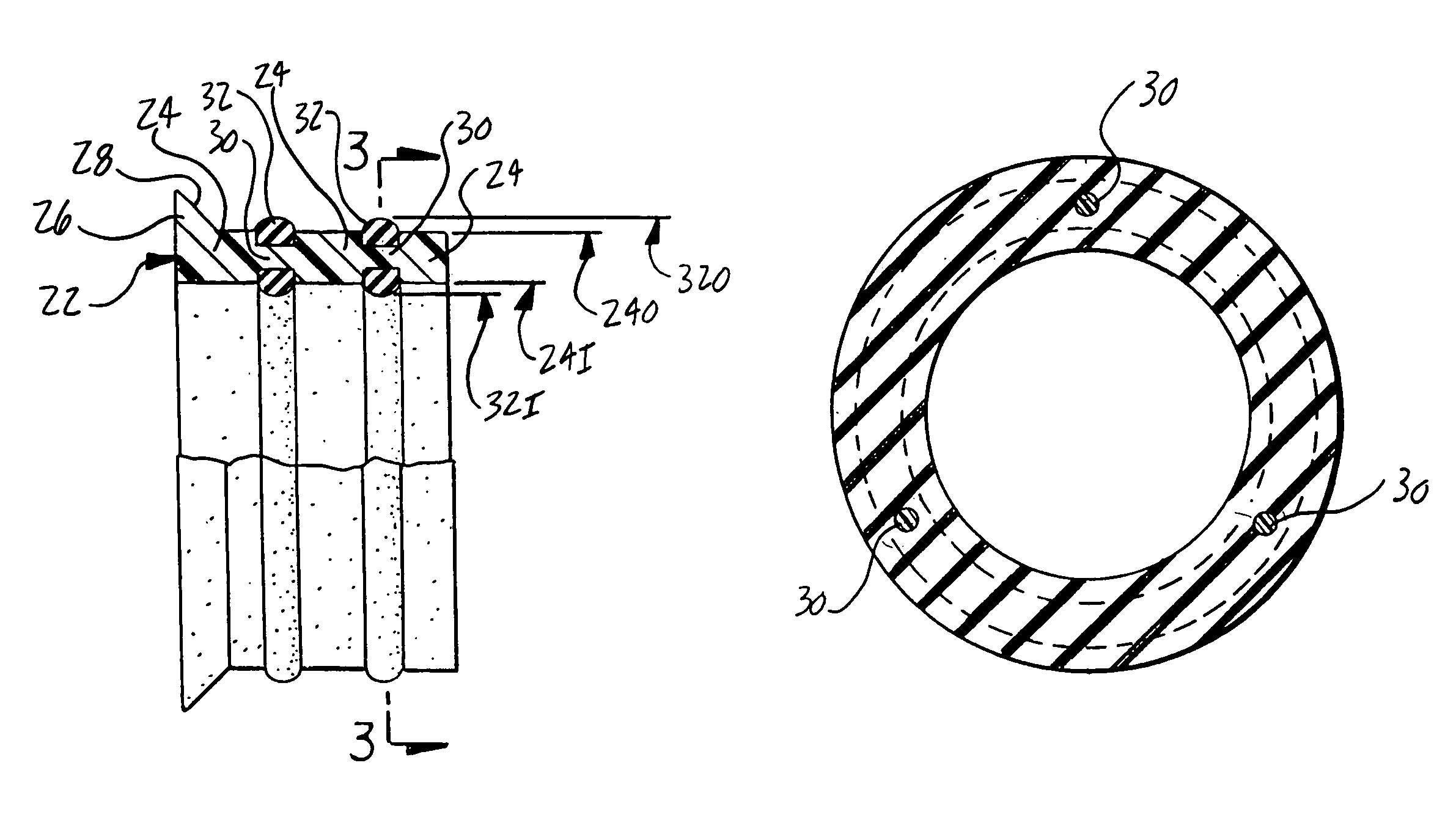
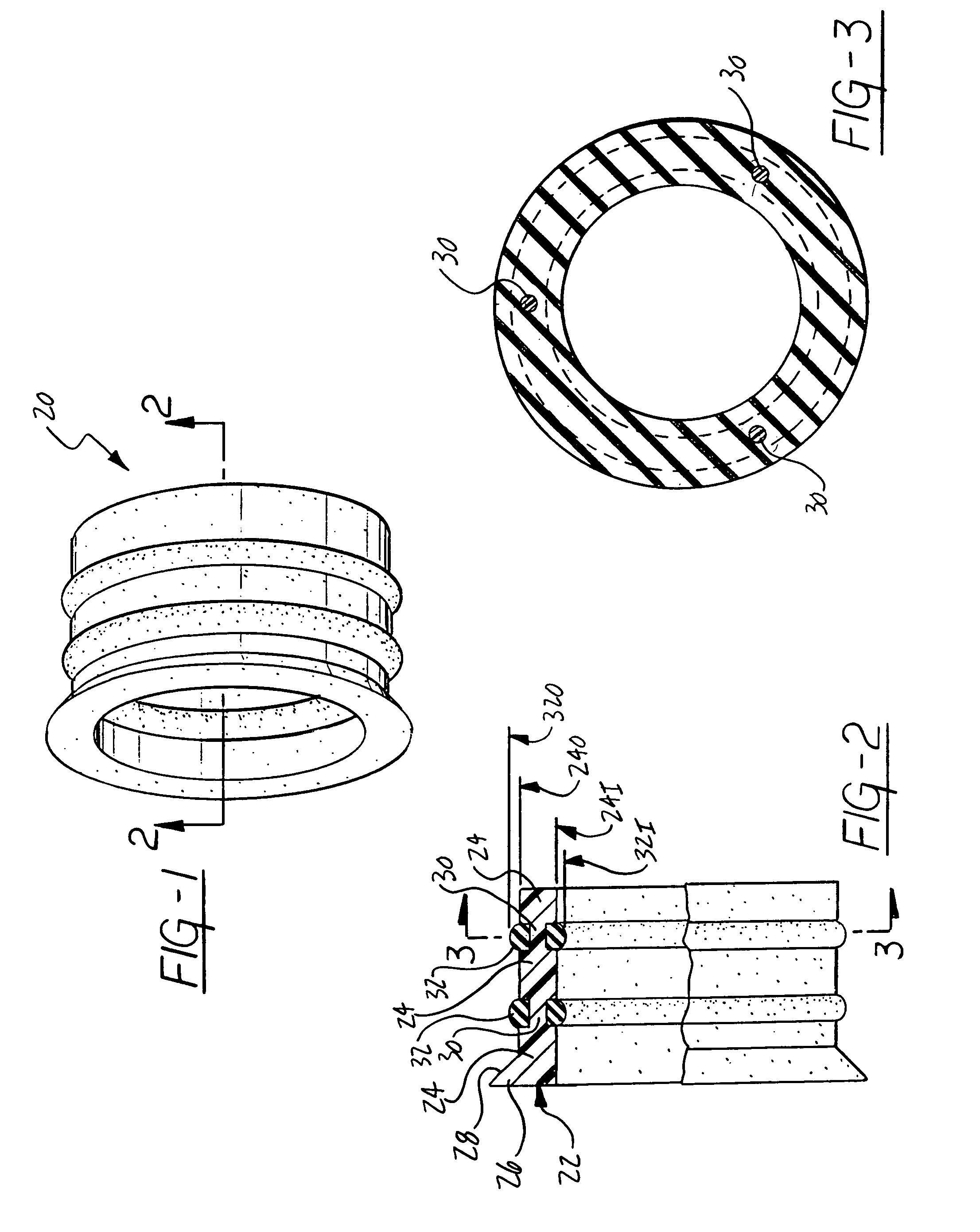
[0035]Referring to the Figures, and particularly to FIG. 1 there is shown a composite sleeve seal 20 according to the preferred embodiment of the present invention. As shown in FIG. 2, the composite sleeve seal 20 is made up of a body portion 22 having spaced apart collar sections 24 that are annular or ring-like in form. The collar sections 24 are preferably composed of a plastic material such as nylon, but may also be composed of a metal or composite material. One of the collar sections 24 may also have a tapered portion 26 having a tapered surface 28. The collar sections 24 have a common inside diameter 241 and outside diameter 240. The collar sections 24 are interconnected by three link segments 30 between each collar section 24. As shown in FIG. 3, the link segments 30 are circumferentially equally spaced apart, and extend axially from the collar sections 24. According to FIG. 2, the link segments 30 are integral with each of the collar sections 24 with which they connect such ...


PUM

PropertyMeasurementUnit
Timeaaaaaaaaaa
Angleaaaaaaaaaa
Diameteraaaaaaaaaa

Abstract

A composite sleeve seal for sealing a conduit connection including a body portion having collar sections spaced apart from one another to define gaps therebetween, and being interconnected to one another by link segments spanning the gaps. A seal portion interposes the collar sections in the gaps and surrounds the link segments to positively interlock the seal portion with the body portion to form the composite sleeve seal as one integral component.

Description

BACKGROUND OF THE INVENTION[0001]1. Field of the Invention[0002]The present invention relates in general to conduit connections for fluid systems. More particularly, the present invention relates to a composite sleeve seal for a fluid-tight conduit connection between male and female tubular members of an automobile air-conditioning system.[0003]2. Description of the Prior Art[0004]In conventional tubular couplings, standard O-rings are used to seal the connection between tubular members. The O-rings are seated in grooves in a male or female tubular member and are compressed by a complementary female or male tubular member, thereby sealing the connection. The O-ring grooves are generally machined or formed into one of the tubular members as part of a tube end-forming step in the manufacturing process. Performing this step involves extensive process cycle time and total piece costs.[0005]U.S. Pat. No. 4,055,359 to McWethy is an example of the prior art tubular coupling described above...

Claims


Application Information

Patent Timeline
IPC IPC(8): F16L21/05F16L17/00F16L5/02
CPCF16L21/02F16L23/16F16L37/0845F16L37/02Y10T29/49297
Inventor CHISNELL, JERRY H.
Owner HUTCHINSON FTS
Why Eureka
Try Eureka