Semiconductor device

a technology of semiconductor devices and dielectric devices, applied in semiconductor devices, transistors, electrical devices, etc., can solve the problems of increased loss in a mounted state for use, increased breakdown potential, increased cost, etc., and achieves reduced resistance, reduced resistance, and increased channel length

Inactive Publication Date: 2005-01-25
RENESAS ELECTRONICS CORP
View PDF12 Cites 9 Cited by
  • Summary
  • Abstract
  • Description
  • Claims
  • Application Information

AI Technical Summary

Benefits of technology

Thus, at corner portions of the quadrangular opening 52 the impurity is radially dispersed and diffused, so that the impurity concentration at each corner portion becomes lower than that at each side portion, and the impurity diffusion length becomes shorter. Such a lowering of the impurity concentration results in easier inversion of the channel surface and easier occurrence of leakage current. The occurrence of leakage current causes a power loss.
According to the above means (1):(a) In each of the quartered trapezoidal source regions, the width c of an outer end of the source region which outer end corresponds to a base of the trapezoid is close to the gate electrode, while the width a of an inner end of the source region which inner end corresponds to an upper side of the trapezoid is exposed into the source contact hole, and thus the source region assumes a divergent shape in the flowing direction of drain current, so that the flow of drain current becomes smooth and ON resistance is decreased. That is, the source region is formed as a pattern wherein the width b of the source region is longer than the width a of the inner end of the source region, and the width c of the outer end of the source region is longer than the width b of the source region. Besides, since the isolation spacing between adjacent source regions is as narrow as 0.3 to 0.4 μm, the width of each source region can be set to a maximum value and ON resistance can be made small.(b) Since there is adopted a structure wherein at each corner portion of the quadrangular cell the source region is not extended to below the gate electrode (gate insulating film), it follows that the source region is not formed in the short channel portion at each cell corner, so that the channel length practically becomes larger and leakage current is diminished.(c) With the above (a) and (b), it is possible to provide a vertical high breakdown voltage MOSFET which permits a decrease of leakage current and of power loss. Further, yield is improved in manufacture by decrease of the leakage current, whereby it is possible to provide a high-quality product at low cost.

Problems solved by technology

In a semiconductor device structure having a pn junction such as a power MOSFET, there occurs leakage current due to for example a defect in the bulk or surface, but if the level of the leakage current is bad, there may be an increase of loss in a mounted state for use, or as the case may be, a breakdown potential increases due to concentration of an electric current in a defective portion.
Also in the device itself, not only its quality but also the yield thereof is deteriorated with an increase of the leakage current level, thus causing an increase of cost.
A main cause of leakage current is a defect in the manufacturing stage such as a defect in the bulk or surface, but as design-related factors of leakage current there are such parameters as channel length and impurity concentration of a channel portion.
From the standpoint of a relation of the channel length and impurity concentration to leakage current, the easier the inversion of channel surface into a reverse conductive type, the easier the flow of current, so by making the channel length larger or by making the impurity concentration higher, the inversion of the channel surface becomes difficult, thus permitting a decrease of leakage current.
But this method gives rise to the problem that ON resistance increases to a great extent, resulting in deterioration of the device performance.

Method used


Image

  • Semiconductor device
  • Semiconductor device
  • Semiconductor device

Examples


first embodiment

(First Embodiment)

FIG. 5 is a schematic plan view of a semiconductor device (semiconductor chip) with a vertical insulated gate field effect transistor (vertical high breakdown voltage MOSFET) built therein according to an embodiment (first embodiment) of the present invention. As shown in FIG. 5, a semiconductor device 1 is of a flat structure having, for example, a length of 4.0 mm, a width of 4.0 mm and a thickness of 0.4 mm. The whole of an upper surface of the semiconductor device 1 serves as a MOS unit cell area 2, in which there are formed a gate pad (gate bonding area) 3 as an external electrode terminal and a source pad (source bonding area) 4. A field limiting area spreads outside the MOS unit cell area 2. A back side of the semiconductor device 1 serves as a drain electrode.

FIG. 6 is a schematic plan view showing the MOS unit cell area 2 partially. As shown in the same figure, unit MOSFETs (cells) 5 are arranged in order longitudinally and transversely. In the present inv...

second embodiment

(Second Embodiment)

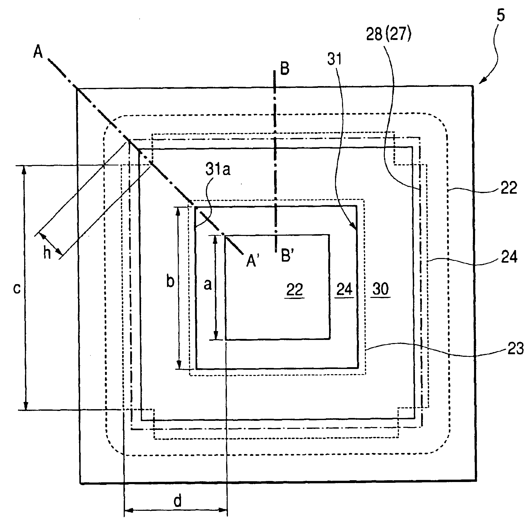
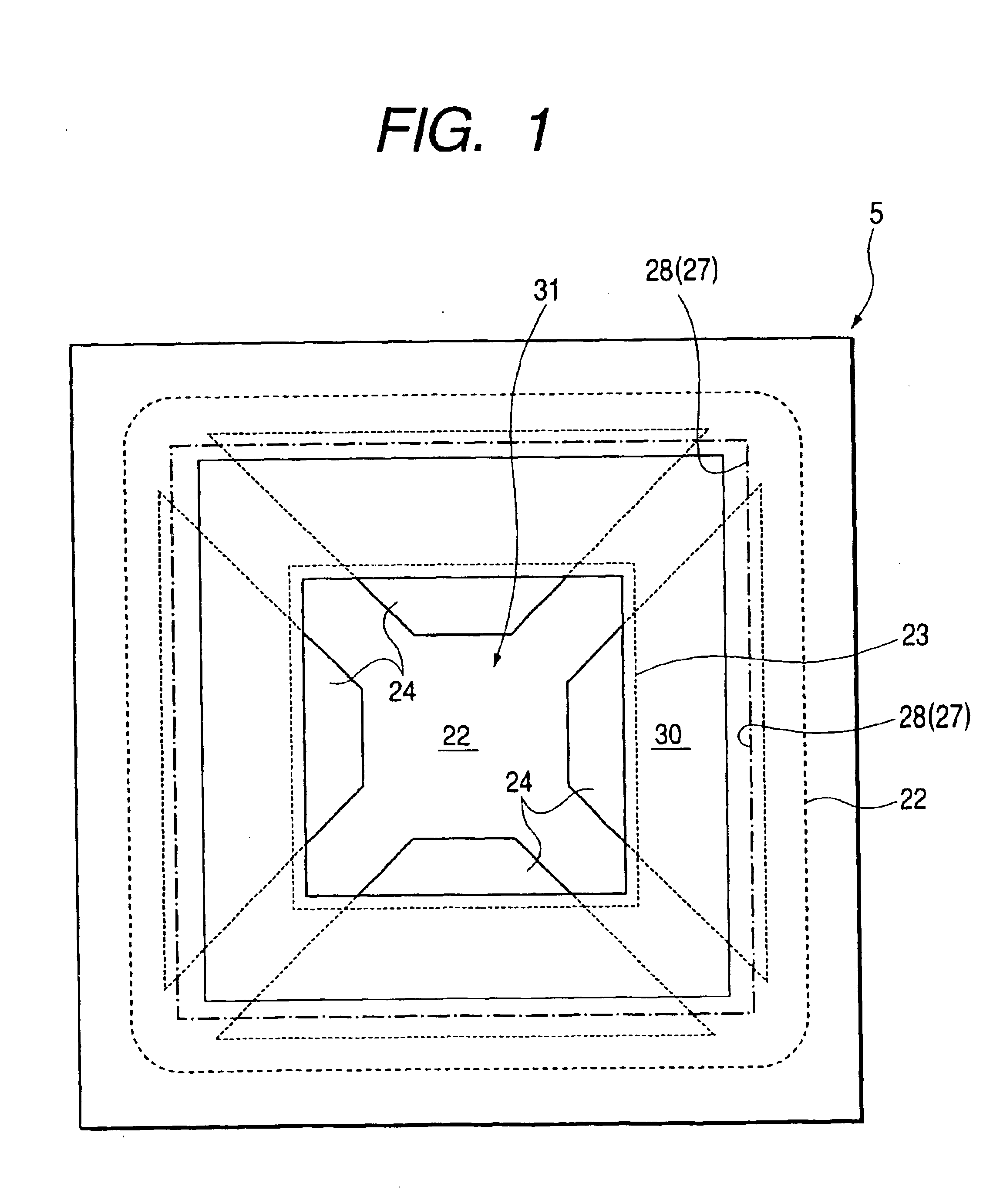
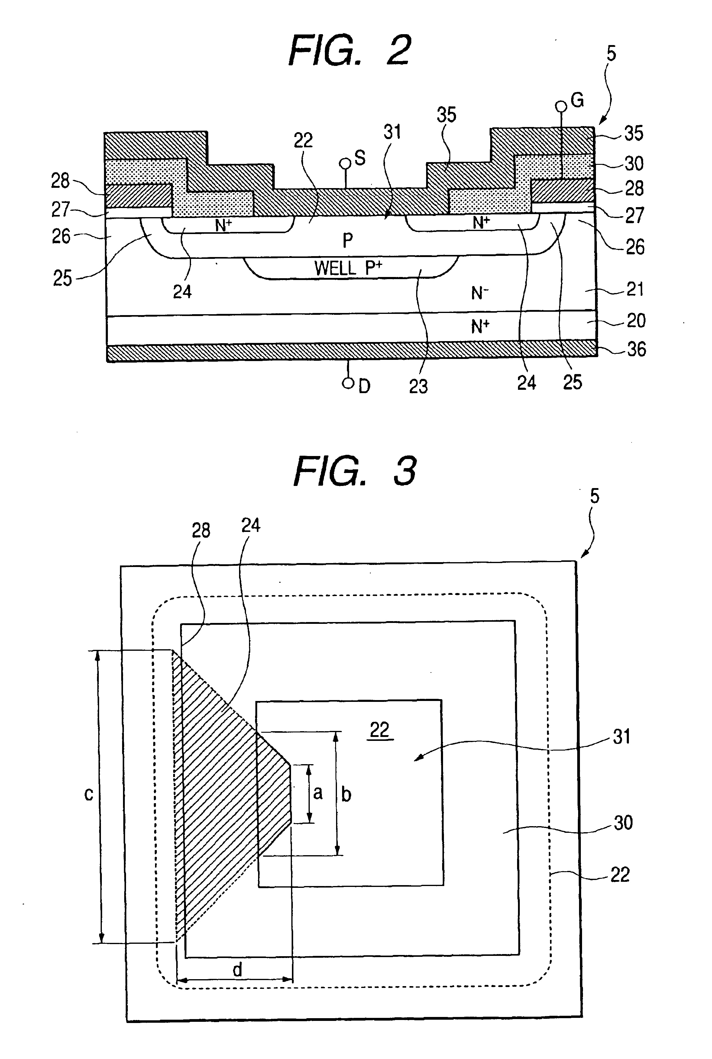
FIG. 9 is a schematic plan view showing a vertical power MOSFET portion according to a further embodiment (second embodiment) of the present invention and FIGS. 10(a) and 10(b) are sectional views taken along lines A-A′ and B-B′ in FIG. 9.

In this second embodiment, in a unit MOSFET (cell) 5, a source region 24 is formed as a quadrangular frame pattern extending along a source contact hole 31, but at the corners of a quadrangular cell the impurity concentration is not uniform and the channel length is short, so at the corner portions the source region 24 is not provided. FIG. 10(b) is a sectional view taken along line B-B′ in FIG. 9. In the same figure, the source region 24 extends up to below a gate insulating film 27 and a gate electrode 28 and a channel 25 is formed. FIG. 10(a) is a sectional view taken along line A-A′ in FIG. 9, showing a portion corresponding to a corner of a quadrangular cell. As shown in the same figure, an outer end portion of the source re...


PUM


Abstract

ON resistance and leakage current of a vertical power MOSFET are to be diminished. In a vertical high breakdown voltage MOSFET with unit MOSFETs (cells) arranged longitudinally and transversely over a main surface of a semiconductor substrate, the cells are made quadrangular in shape, and in each of the cells, source regions whose inner end portions are exposed to the interior of a quadrangular source contact hole are arranged separately and correspondingly to each side of the quadrangle. Each source region is trapezoidal in shape, and a lower side of the trapezoid is positioned below a gate electrode (gate insulating film), while an upper side portion of the trapezoid is exposed to the interior of the source contact hole. The four source regions are separated from one another by diagonal regions of the quadrangle.

Description

BACKGROUND OF THE INVENTIONThe present invention relates to a technique applicable effectively to a semiconductor device, e.g., a vertical high breakdown voltage MOSFET (Metal Oxide Semiconductor Field Effect Transistor) which permits ON resistance to be made small and permits reduction of a device area.A vertical high breakdown voltage MOSFET, i.e., a power MOSFET, has various characteristics such as being superior in frequency characteristic, high in switching speed and capable of being driven at a low power. For this reason the MOSFET in question is used in various industrial fields.For increasing output, the power MOSFET adopts a structure wherein a large number of unit MOSFETs (cells) are arrayed over a main surface of a semiconductor substrate. Examples of cell shapes include quadrangular, hexagonal, and circular shapes. In the case of circular or hexagonal cells, there is adopted a so-called triangular array in which three adjacent cells are centered respectively on vertices ...

Claims


Application Information

Patent Timeline
Patent Type & Authority Patents(United States)
IPC IPC(8): H01L29/02H01L29/66H01L29/78H01L29/06
CPCH01L29/0696H01L29/7802H01L29/0869H01L2224/0603H01L2224/48247H01L2924/13091H01L2924/13062H01L2924/00
Inventor ISHIZAKA, KATUOIIJIMA, TETSUO
Owner RENESAS ELECTRONICS CORP
Why Eureka
Try Eureka