Diffusing sheet, surface light source unit, and transmission type display

a technology of diffusion sheet and transmission type, applied in the field of diffusion sheet, can solve the problems of reducing optical efficiency, reducing the number of optical sheets needed for this unit, poor light-converging properties of conventional surface light source units of direct type, etc., and achieves the effects of reducing illumination non-uniformity, enhancing diffusion properties, and further enhancing diffusion properties

Inactive Publication Date: 2008-08-05
DAI NIPPON PRINTING CO LTD
View PDF12 Cites 22 Cited by
  • Summary
  • Abstract
  • Description
  • Claims
  • Application Information

AI Technical Summary

Benefits of technology

[0027]The present invention can show the following actions and effects:
[0038](11) The two or more diffusing sheets are arranged in such a manner that the directions in which the diffusion lens arrays on the diffusing sheets exert their light-diffusing actions become perpendicular to each other. It is therefore possible to independently control the viewing angles in two directions that are at right angles. It is also possible to make full use of light, so that the brightness of the illumination light becomes higher.

Problems solved by technology

Such a conventional surface light source unit of direct type is poor in the light-converging properties although the number of optical sheets needed for this unit is great.
However, this conventional way of improvement causes reduction in optical efficiency, and also makes the transmission type display member such as an LCD panel complex in construction, which leads to increase in cost.
Another disadvantage of the conventional surface light source unit of direct type has been that the light intensity (luminance) on the display member tends to be non-uniform depending on the distance from the cathode ray tubes (i.e., whether a certain point on the display member is close to the cathode ray tube or to the space between the cathode ray tubes that are arranged in parallel).
This method has been disadvantageous in that the display has an increased total thickness.
This method has been disadvantageous in that it causes decrease in the amount of usable light.
This method has been disadvantageous in that it causes decrease in the amount of usable light, like the above-described method.
Thus, this method still has been at a disadvantage in that the brightness of light on the display screen varies depending on the position from which the display screen is observed.

Method used


Image

  • Diffusing sheet, surface light source unit, and transmission type display
  • Diffusing sheet, surface light source unit, and transmission type display
  • Diffusing sheet, surface light source unit, and transmission type display

Examples


embodiment 1

[0072]First, a transmission type display according to the first embodiment of the present invention will be described with reference to FIGS. 1 to 17.

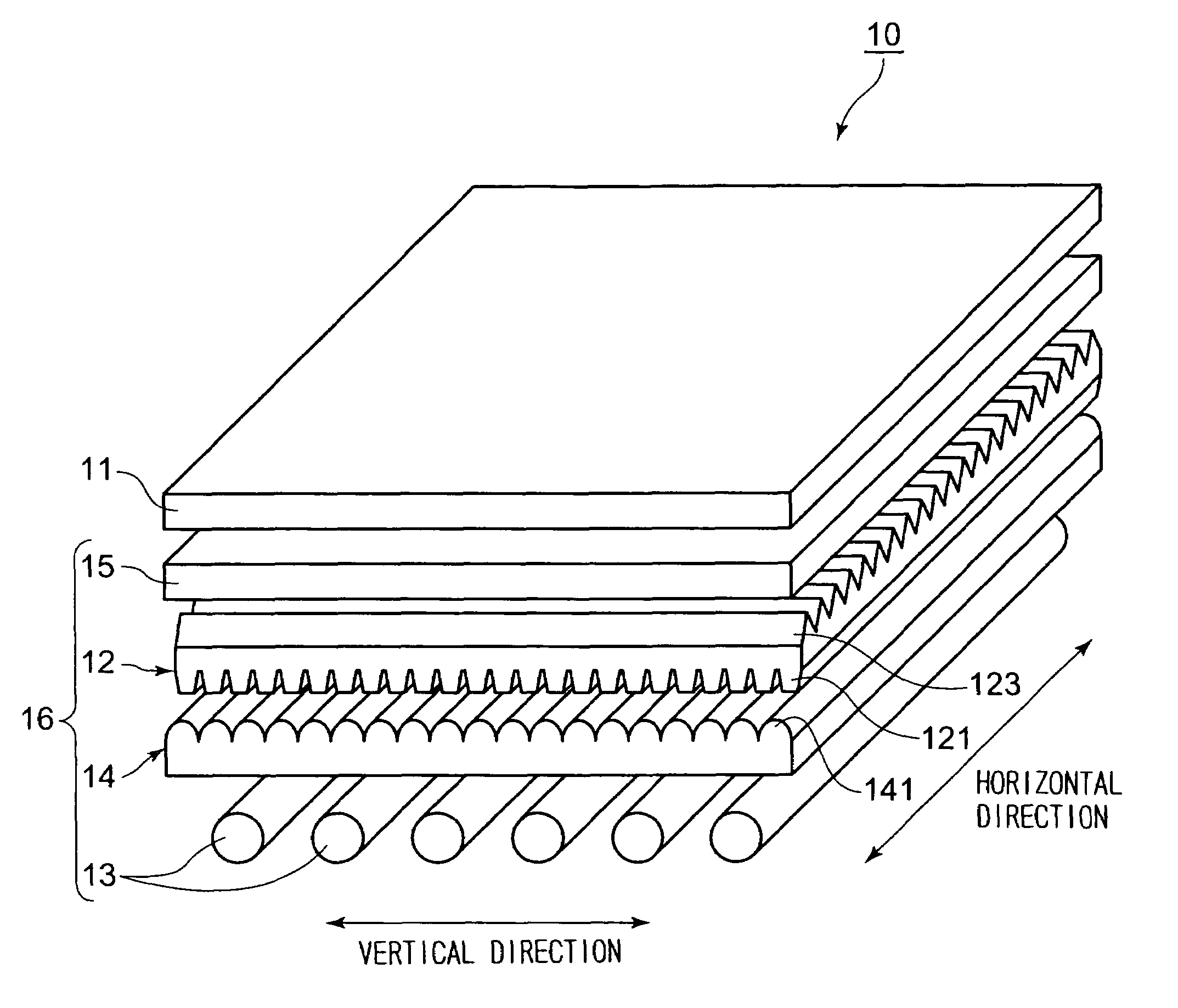
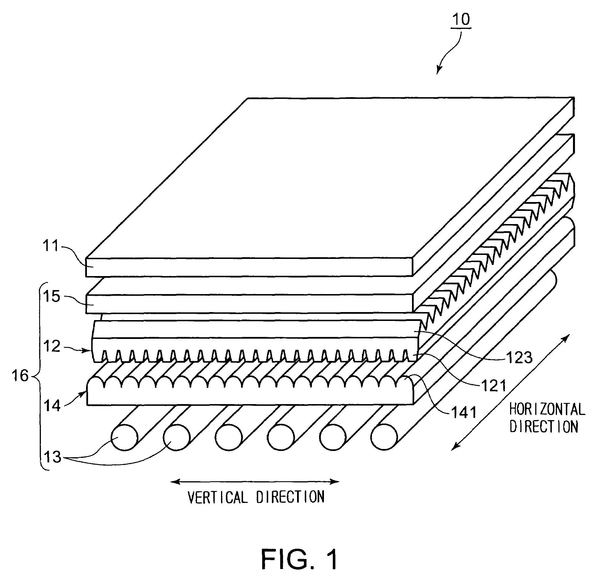
[0073]As shown in FIG. 1, a transmission type display 10 according to the first embodiment of the present invention is a liquid crystal display of transmission type, in which liquid crystal display elements control transmission / non-transmission of light to display image information, and comprises an LCD panel (transmission type display member) 11 and a surface light source unit 16 that illuminates the LCD panel from its rear. The surface light source unit 16 comprises a convergent sheet 12, cathode ray tubes 13, a diffusing sheet 14, and a reflective polarizer 15, and illuminates, from the rear, the LCD panel 11 on which an image pattern has been produced according to image information, thereby forming an image on the LCD panel 11. Those figures, including FIG. 1, to which reference is made in the following description are diagrammatic...

embodiment 2

[0152]Next, a transmission type display according to the second embodiment of the present invention will be described hereinafter with reference to FIGS. 18 to 21. The second embodiment of the present invention is basically the same as the first embodiment shown in FIGS. 1 to 17, except that, instead of the convergent sheet 12 according to the first embodiment, a convergent sheet 22 having light-entering-side unit lenses 221 that are an improvement in shape over the light-entering-side unit lenses 121 is used in the surface light source unit in the transmission type display. Like reference numerals designate like or corresponding parts throughout FIGS. 1 to 17 that show the first embodiment and FIGS. 18 to 21 that show the second embodiment, and explanation that has been given already on such parts will be omitted in the following description.

[0153]A convergent sheet 22 according to the second embodiment of the present invention, whose cross section is shown in FIG. 18, has on its l...

embodiment 3

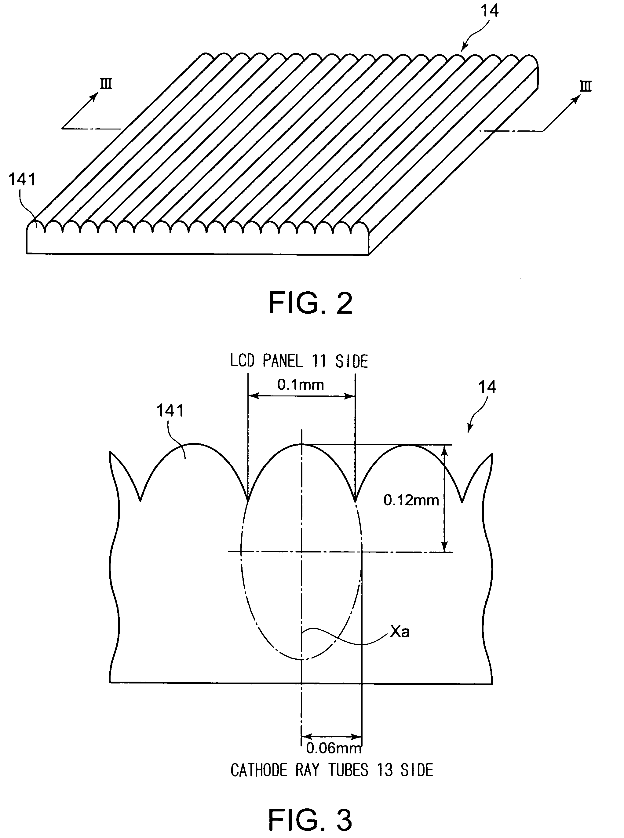
[0164]A transmission type display according to the third embodiment of the present invention will be described hereinafter with reference to FIGS. 22 to 26B. The third embodiment of the present invention is basically the same as the first embodiment shown in FIGS. 1 to 17, except that, instead of the diffusing sheet 14 according to the first embodiment, a diffusing sheet 24 having a diffusion lens array 241 that is an improvement in shape over the diffusion lens array 141 on the diffusing sheet 14 is used for the surface light source unit in the transmission type display. Like reference numerals designate like or corresponding parts throughout FIGS. 1 to 17 that show the first embodiment and FIGS. 22 to 26B that show the third embodiment, and explanation that has been given already on such parts will be omitted in the following description.

[0165]As shown in FIG. 22, a diffusing sheet 24 according to the third embodiment of the present invention is a sheet for diffusing light from th...


PUM

PropertyMeasurementUnit
half-angle of diffusionaaaaaaaaaa
half-angleaaaaaaaaaa
angleaaaaaaaaaa

Abstract

A diffusing sheet, a surface light source unit, and a transmission type display that can attain uniform illumination so that the brightness of light on the display screen appears uniform regardless of the position from which the display screen is observed. The diffusing sheet includes, on its light-emerging side surface, a diffusion lens array having a plurality of unit lenses, each unit lens being in a shape equivalent to a part of an elliptic cylinder having an elliptical cross section. The surface light source unit includes the diffusing sheet and a convergent sheet 12 that has a plurality of unit lenses 121 having almost trapezoidal cross sections, formed on one surface thereof. It is possible to attain uniform illumination by diffusing light from cathode ray tubes in the surface light source unit, and, at the same time, to converge the light serving as backlight to enhance optical efficiency.

Description

BACKGROUND OF THE INVENTION[0001]1. Field of the Invention[0002]The present invention relates to a display such as a liquid crystal display, and more particularly to a diffusing sheet for use in a surface light source unit that illuminates a transmission type liquid crystal display or the like from its rear, to a surface light source unit, and to a transmission type display using the diffusing sheet and the surface light source unit.[0003]2. Background Art[0004]A variety of surface light source units that are used to illuminate transmission type liquid crystal displays or the like from their rear have been proposed and put into practical use. Such surface light source units are broadly classified into the edge light type and the direct type according to the mode of conversion of a non-surface light source to a surface light source.[0005]Of these, a surface light source unit of direct type is so constructed that light is introduced to the rear of a transmission type display member se...

Claims


Application Information

Patent Timeline
Patent Type & Authority Patents(United States)
IPC IPC(8): G03B21/60G02B27/10G03B21/56F21S2/00F21Y103/00G02B3/00G02B3/06G02B3/08G02B5/02G02F1/1335G02F1/13357G09F9/00
CPCG02B3/0031G02B3/005G02B3/0056G02B3/0062G02B19/0028G02B3/08G02B19/0047G02B3/04G02F2001/133607G02F1/133607B42F7/065B42D15/0006B42D15/008
Inventor GOTO, MASAHIROIIDA, MITSURUTOKUHARA, WATARU
Owner DAI NIPPON PRINTING CO LTD
Why Eureka
Try Eureka