Method and system for transmitting signals with reduced spurious emissions

Inactive Publication Date: 2008-08-05
SHARED SPECTRUM
View PDF15 Cites 10 Cited by
  • Summary
  • Abstract
  • Description
  • Claims
  • Application Information

AI Technical Summary

Benefits of technology

[0021]It is a first object of the present invention to provide an imp

Problems solved by technology

Existing amplifiers will create significant out-band emission

Method used


Image

  • Method and system for transmitting signals with reduced spurious emissions
  • Method and system for transmitting signals with reduced spurious emissions
  • Method and system for transmitting signals with reduced spurious emissions

Examples


Example

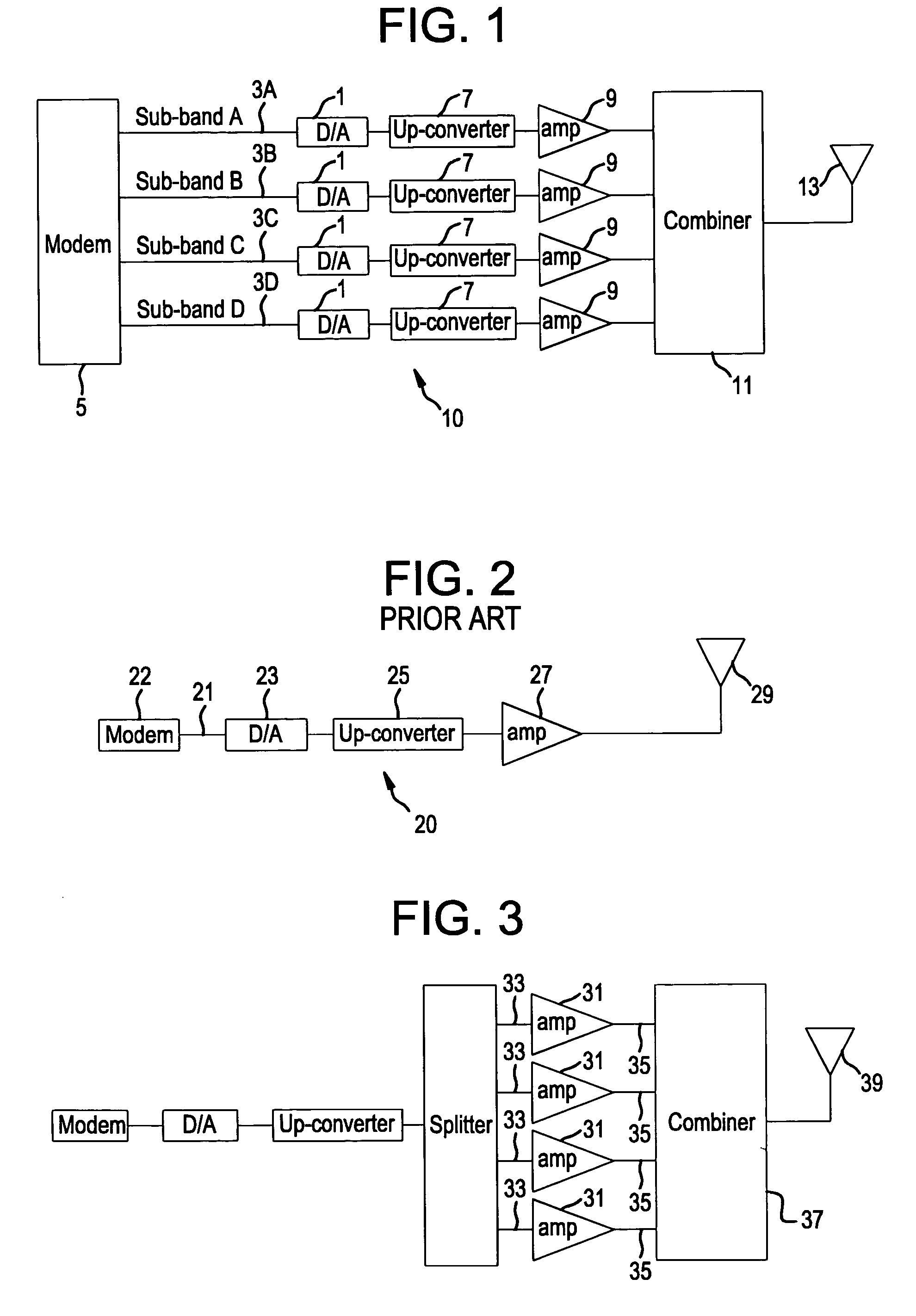
[0050]The inventive sub-band transmitter system greatly reduces spurious emissions by amplifying narrow spectrum sub-band “slices” and then combining them to obtain the full spectrum. FIG. 1 shows an exemplary system architecture 10 that uses multiple digital to analog (D / A) converters 1 that receive different waveforms or ‘sub-bands’3A-3D that are produced by a modem 5. In this embodiment, the sub-band waveform's bandwidth is approximately one quarter the final signal bandwidth, but the bandwidth may vary depending on the number of sub-bands. The sub-band signals 3A-3D are converted to analog using the D / A converters 1, up converted at 7, amplified at 9 using four amplifiers, and then combined using combiner 11 before being sent to the antenna 13.

[0051]For comparison, FIG. 2 shows a conventional architecture with a single transmitter chain 20, using a single path that converts the signal 21 from the modem 22 to analog at 23, up-converts at 25, amplifies at 27, and then sends the si...


PUM


Abstract

An RF power amplifier architecture minimizes spurious emissions by breaking the transmitted signal into narrow spectrum sub-bands, amplifying each separately, and then combining the signals for transmission purposes.

Description

[0001]This application claims priority under 35 USC 119(3) based on provisional patent application No. 60 / 477,155 filed on Jun. 10, 2003.[0002]This invention was made with Government support under Contract F30602-03-C-0141 awarded by the Air Force. The Government has certain rights in this invention.FIELD OF THE INVENTION[0003]The present invention is directed to an RF power amplifier architecture that significantly reduces an amplifier's out-of-band emissions.BACKGROUND ART[0004]A principle goal of communication systems is to maximize spectrum efficiency via the use of broadband waveforms transmitting over non-contiguous spectrum and to minimize the waveform's adjacent power level. A goal of the Defense Advanced Research Projects Agency (DARPA) in Future Combat Systems (FCS) and other programs is the development of the orthogonal frequency-division modulation (OFDM) for use with tactical systems. The OFDM waveform has perhaps the best combination of multipath and Eb / N0 properties o...

Claims


Application Information

Patent Timeline
IPC IPC(8): H04L25/49H03FH03F1/32H04B1/04H04B1/69H04K1/02H04L27/26
CPCH03F1/3229H04B1/0475H04B1/71635H04B1/0483H04B2001/0408H04L27/2626H03F3/24H04L27/26265
Inventor MCHENRY, MARK ALLEN
Owner SHARED SPECTRUM
Why Eureka
Try Eureka