Non-volatile memory card with autarkic chronometer

hronometer technology, applied in the field of semiconductor devices and methods, can solve the problems of hard to enforce the deactivation of a non-volatile memory card at the end of the expected lifetime, memory cards degrade with time, and many customers do not read such information, and achieve the effect of easy detection

Inactive Publication Date: 2008-08-12
POLARIS INNOVATIONS LTD
View PDF10 Cites 39 Cited by
  • Summary
  • Abstract
  • Description
  • Claims
  • Application Information

AI Technical Summary

Benefits of technology

[0015]In another aspect of the present invention, the memory card also comprises a signaling means, which is controlled by the controller. In the corresponding embodiment the power supply of the memory card also powers the controller. In such an arrangement not only does the chronometer become autarkic, but also the controller. Consequently, the controller can remain operational even if the memory card is not connected to an external host system. Once a predefined point in time has been reached, for example a predetermined time when it becomes necessary to copy the data from the current non-volatile memory card to a new non-volatile memory card, the controller can activate the signaling means to indicate this need to a person entrusted with the data maintenance. In a large data archive comprising thousands of non-volatile memory cards, such an automatic signaling from the memory card makes it easy to detect memory cards that need replacement or other types of maintenance.

Problems solved by technology

Although non-volatile memory cards provide a reliable storage solution, even such memory cards degrade with time.
However, it is a disadvantage of the current generation of non-volatile memory cards that it is very hard to enforce the deactivation of a non-volatile memory card at the end of the expected lifetime once it has been released to a customer.
However, many customers do not read such information or do not act according to them.
Unfortunately these methods are not as flexible as measuring the wall clock time directly.
An additional disadvantage of these methods is that such observations can only be made and analyzed as long as the non-volatile memory card is connected to a host system.
Consequently, such methods are unsuitable for long-term storage solutions based on non-volatile memory cards, such as data archives comprising a multitude of NVMCs, which are only connected to an external, electrical device very infrequently.
For such applications the number of read and write cycles or the operational lifetime is very low and not suitable to evaluate the device's lifetime.

Method used


Image

  • Non-volatile memory card with autarkic chronometer
  • Non-volatile memory card with autarkic chronometer
  • Non-volatile memory card with autarkic chronometer

Examples


first embodiment

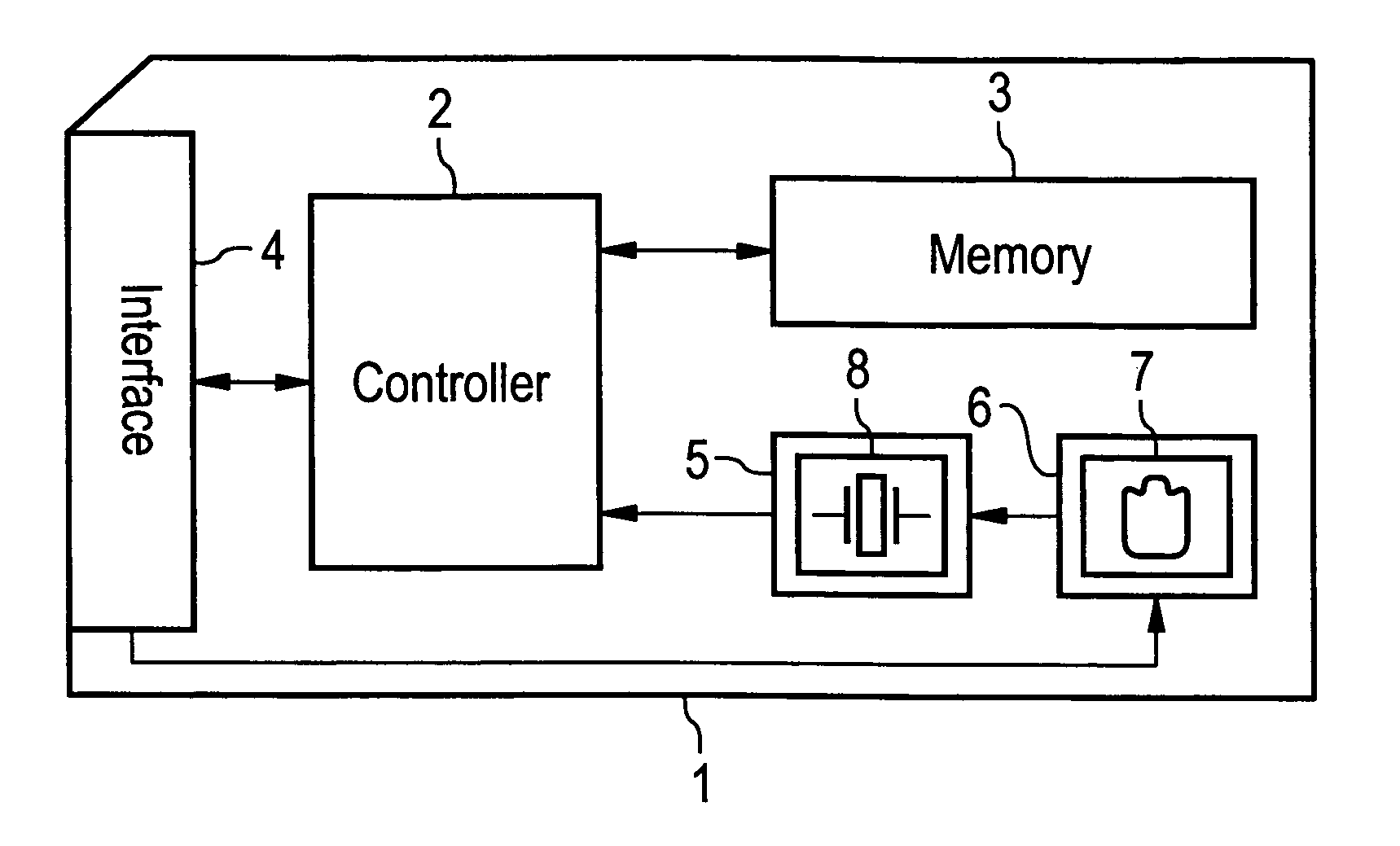
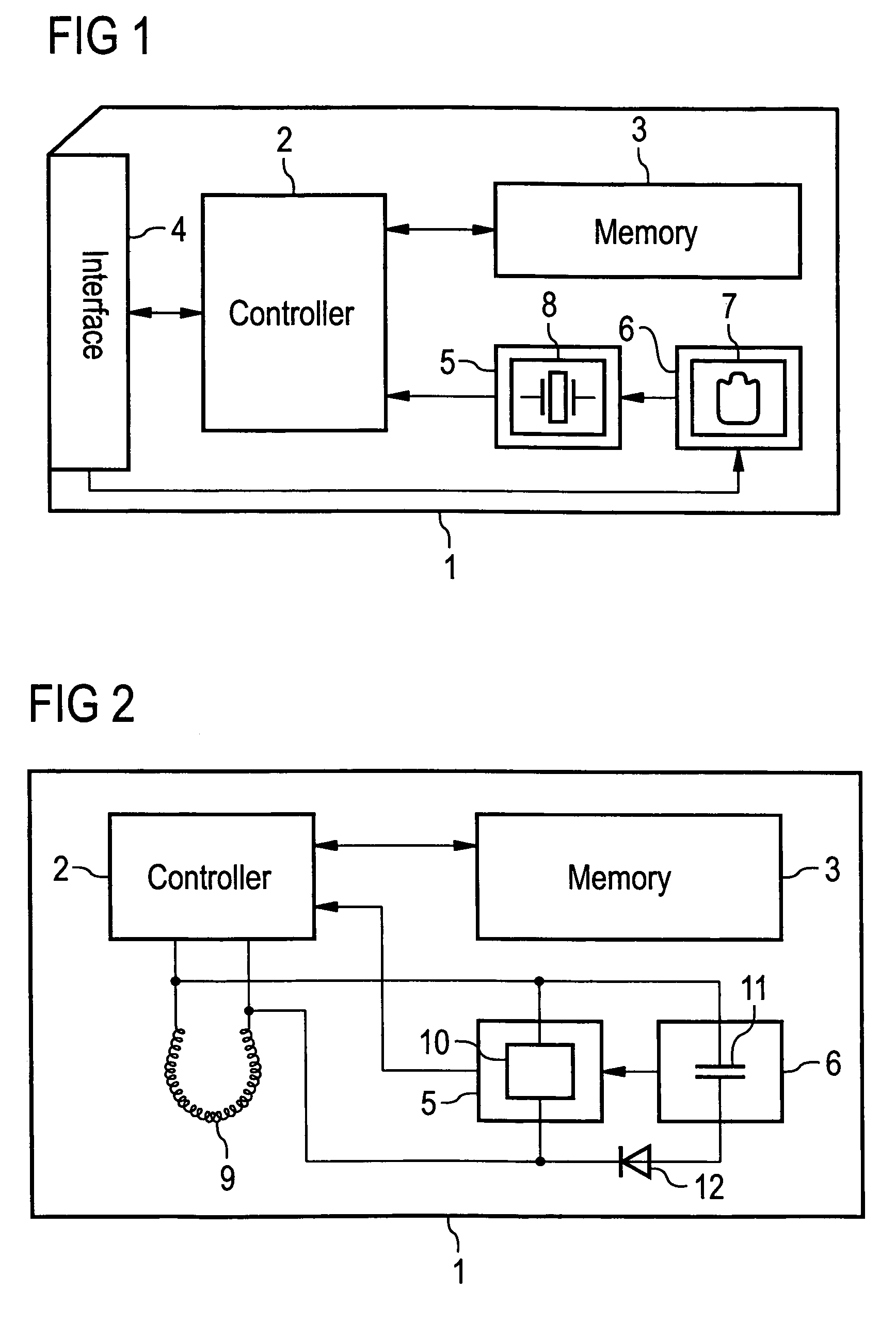
[0025]FIG. 1 shows the present invention. A memory card 1, for example an xD-Picture Card, a SmartMedia (SM) card or a Memory Stick (MS), comprises a controller 2 and a non-volatile memory module 3. The memory card 1 further comprises an interface 4 for the exchange of data with an external, electronic device such as a host computer (not shown). The controller 2 is connected to the memory module 3 and the interface 4 and controls the data exchange between the memory module 4 and the external, electronic device. The interface 4 is implemented using contacts for forming an electrical connection for transmitting data and power from and to the host system.

[0026]The memory card 1 further comprises a chronometer 5 and a power supply 6. The power supply 6 comprises an energy store, in the exemplary embodiment given by a battery 7. In the exemplary embodiment the battery 7 is rechargeable and is connected to the interface 4. The battery 7 has a capacity large enough to supply the chronomete...

second embodiment

[0031]FIG. 2 shows the present invention. The exemplary embodiment shows a memory card 1, for example a radio frequency identity (RFID) card, comprising a controller 2 and a non-volatile memory module 3. As in the last embodiment, the memory card 1 comprises a power supply 6 and a chronometer 5. Unlike the last embodiment, the memory card 1 does not provide an electrical interface to directly connect the memory card 1 to an external, electrical device. Instead, the memory card 1 comprises an antenna 9, which serves as the interface and allows to couple the memory card 1 wirelessly to an external, electrical device.

[0032]In addition, the chronometer 5 contains a time receiving module 10, which is connected to the antenna 9 and configured to receive the current time from a publicly available time signal. An example of such a publicly available time signal is the long wave radio signal emitted by the DCF 77 radio transmitter, which provides the current date and time in the Middle Europ...

third embodiment

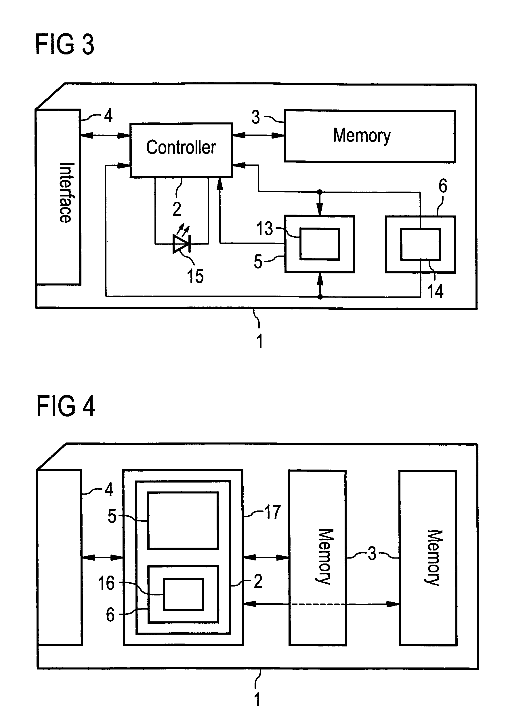
[0037]FIG. 3 shows the present invention. A memory card 1, for example a USB Flash drive or a Compact Flash (CF) card, comprises a controller 2, a non-volatile memory module 3, an interface 4 for connecting the memory card 1 to an external, electrical device, a chronometer 5 and a power supply 6. The chronometer 5 comprises a decay time measurement unit 13, which is capable of estimating the time based on an observed decay process of a chemical compound or element, for example a radioactive substance. The power supply 6 comprises a solar cell 14 and a rechargeable battery 7 (not shown). The memory card 1 further comprises a signaling element 15, in the example of the present embodiment a light emitting diode (LED), connected to the controller 2. The power supply 6 provides the chronometer 5 and the controller 2 with electrical energy.

[0038]Because in this exemplary embodiment the controller 2 is powered by the power supply 6, the controller 2 can operate independently from an extern...


PUM


Abstract

A non-volatile memory card is described, which comprises a chronometer powered by an autarkic, card-internal power supply with a long-term energy store. The chronometer is connected to a card internal controller, such that the chronometer can provide the current time to the controller independent of a host system.

Description

TECHNICAL FIELD[0001]The present invention relates generally to a semiconductor device and methods, a more particularly to a non-volatile memory card with autarkic chronometer.BACKGROUND[0002]Non-volatile memory cards (NVMCs) are becoming more and more popular. They are now widely used in many applications, notably in storage solution for digital consumer devices such as digital cameras or personal audio equipment. In such applications the data stored on the memory card is usually copied to another device like a personal computer or from another medium like an Audio-CD, which serves as a long-term storage facility. Consequently long-term storage of data on non-volatile memory cards has not been an issue yet.[0003]As prices for such memory cards go down, they are also used in other application areas, e.g., for long-term storage of all kinds of data. Although non-volatile memory cards provide a reliable storage solution, even such memory cards degrade with time. For that reason it is ...

Claims


Application Information

Patent Timeline
Patent Type & Authority Patents(United States)
IPC IPC(8): G06K19/06
CPCG11C16/349
Inventor WINKLER, OTTO
Owner POLARIS INNOVATIONS LTD
Why Eureka
Try Eureka