Electromechanical tactile cell assembly

a technology of electromechanical and tactile cells, applied in the field of can solve the problems of increasing the manufacturing cost associated with each braille cell, the accuracy of hand-soldering manufacturing techniques, and the inability to manufacture and maintain electromechanical tactile cell assemblies, so as to improve the manufacturability and reliability of the device, improve the accuracy of hand-soldering manufacturing techniques, and improve the effect of tactile pin maintenance and bimorph reed replacemen

Active Publication Date: 2008-08-12
FREEDOM SCI
View PDF11 Cites 15 Cited by
  • Summary
  • Abstract
  • Description
  • Claims
  • Application Information

AI Technical Summary

Benefits of technology

[0018]As such, the present invention provides improvements in manufacturability and maintenance of electromechanical tactile cell assemblies. The use of a novel multiple element conductive support and a conductive fulcrum pin eliminates the need for lead wires and hand-solder joints, thereby improving both manufacturability and reliability of the device. Tactile pin maintenance and bimorph reed replacement are greatly simplified with the present invention. Additionally, the present invention enables the use of a tactile pin cap

Problems solved by technology

The Braille cells known in the art have not been designed for manufacturability and ease of repair and replacement.
The need for such special metallic plating and individual attachment of the leads increases the manufacturing costs associated with each Braille cell.
This precise positioning and alignment of the reeds with the upward trajectory of the tactile pins proves to be very difficult with hand-soldering manufacturing techniques.
Addi

Method used


Image

  • Electromechanical tactile cell assembly
  • Electromechanical tactile cell assembly
  • Electromechanical tactile cell assembly

Examples


Embodiment Construction

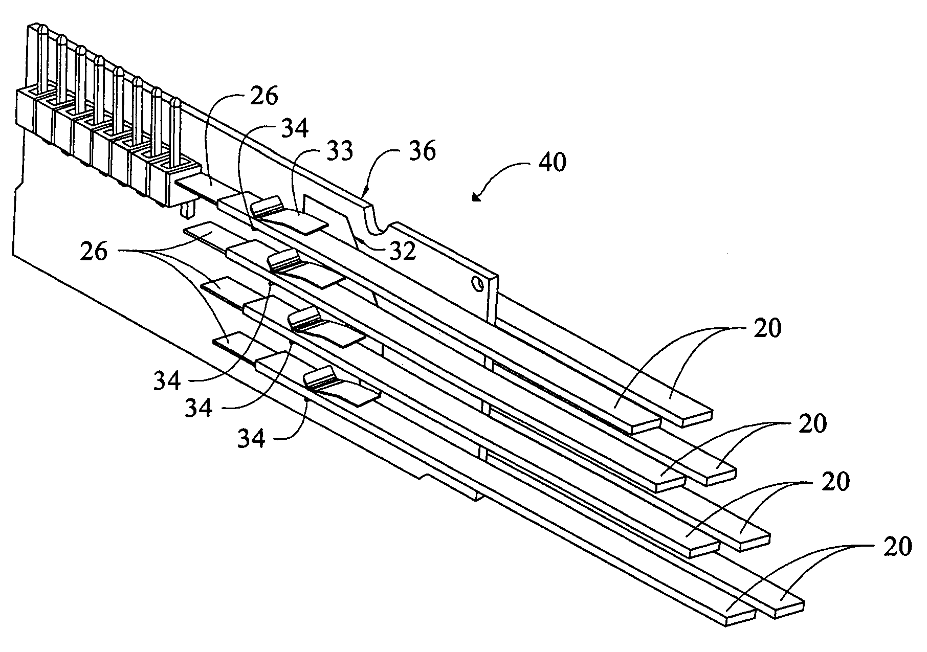
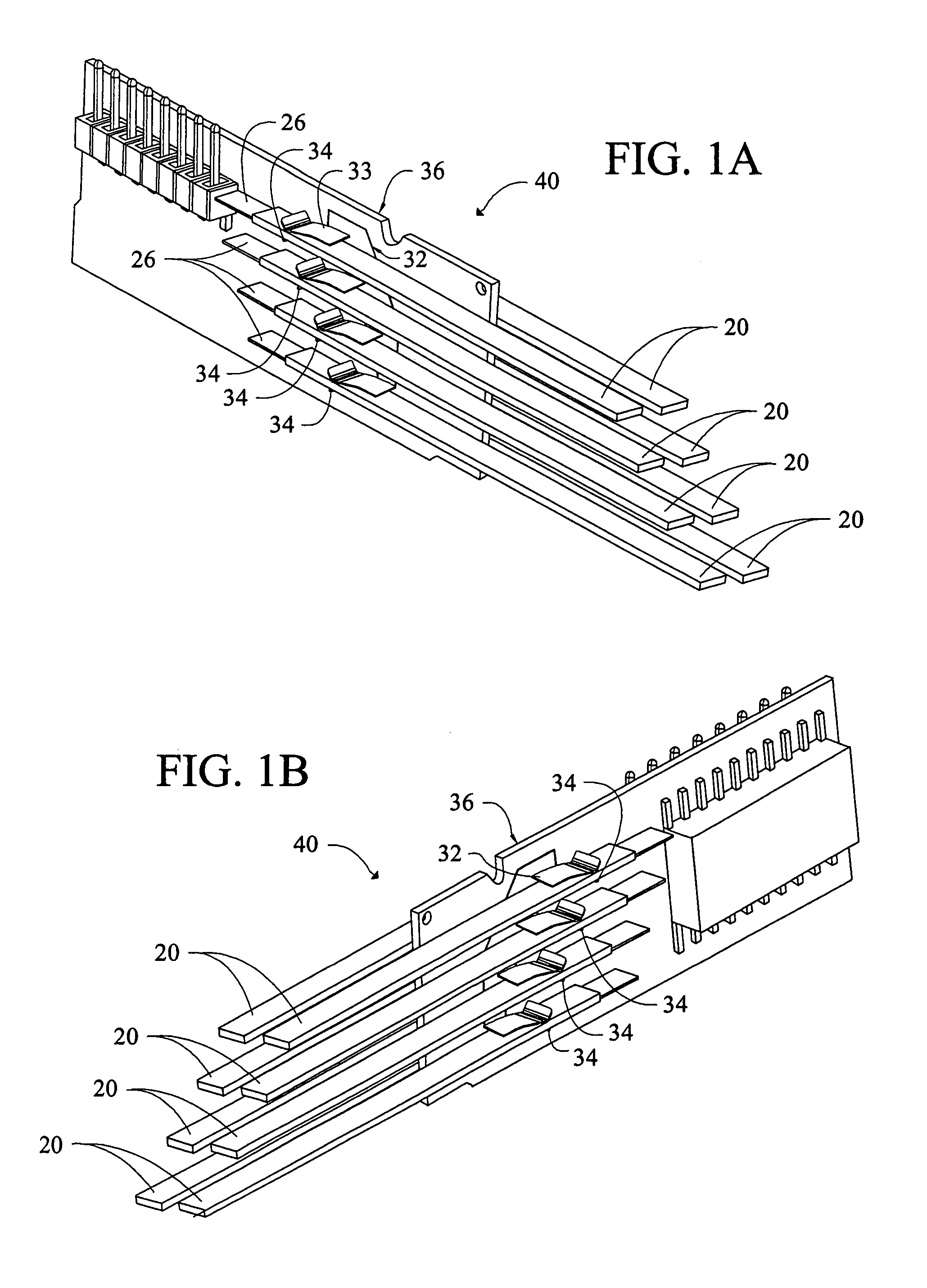
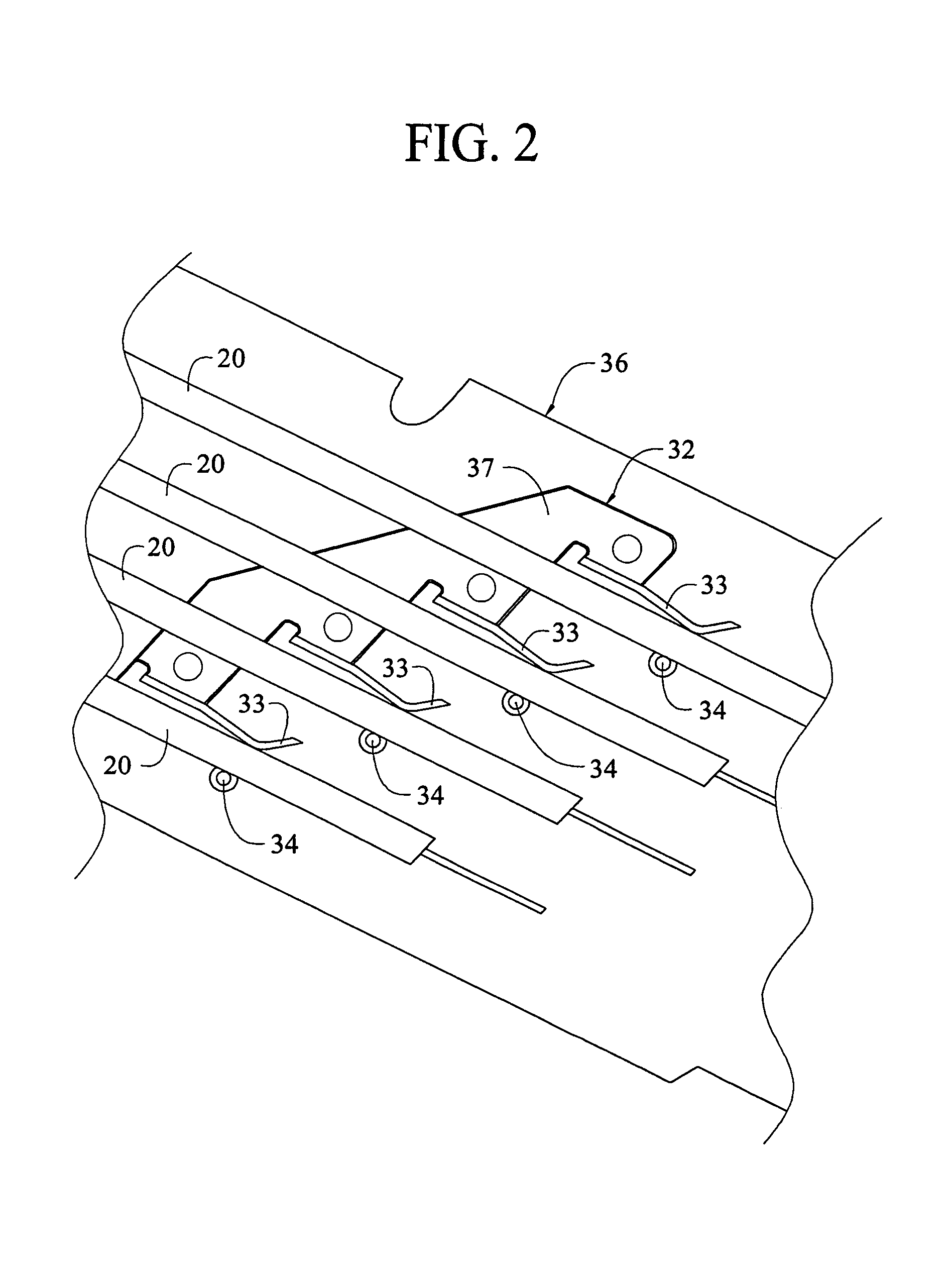
[0027]Referring now to FIGS. 1A and 1B there are shown perspective views of opposite sides of an electromechanical tactile cell 40 incorporating features of the present invention. While alternations are possible to the number and placement of bimorph reeds 20 without departing from the invention, FIGS. 1A and 1B illustrate an embodiment in which eight reeds 20 are conductively secured to a printed circuit board 36, four on each side. The reeds are held in place using a multiple element conductive support 32 in combination with a conductive fulcrum pin 34. In addition to securing the piezoelectric reed to the printed circuit board, these support elements also provide electrical contact and assist with proper alignment of the reeds. To reduce manufacturing costs, the multiple element conductive support 32 and the conductive fulcrum pin 34 are adapted for surface mount technology to be placed on the printed circuit using automated placement equipment. The piezoelectric reeds are then i...


PUM


Abstract

The present invention discloses an electromechanical tactile cell assembly comprising a plurality of piezoelectric element reeds, each one of the piezoelectric element reeds being bendable at an elongated end portion when a voltage is applied to the reed, a plurality of conductive fulcrum pins secured to a printed circuit board, and a plurality of multiple element conductive supports secured to a printed circuit board, each multiple element conductive support, in combination with the plurality of conductive fulcrum pins, adapted to secure a plurality of piezoelectric reeds, corresponding to the plurality of conductive fulcrum pins, to the printed circuit board. The electromechanical tactile cell is adaptable for use with a Braille display.

Description

CROSS REFERENCE TO RELATED APPLICATION[0001]This application claims priority to Provisional Patent Application No. 60 / 481,979 filed, Jan. 30, 2004.BACKGROUND OF INVENTION[0002]A Braille display is an electromechanical device that connects to a computer by way of a serial or parallel cable. The display consists of a line of electromechanical tactile cells, each with six or eight pins that move up and down to represent the dots of a Braille cell. The display is used to represent a line of text on a computer screen. Each cell has six or eight tactile pins that are driven by electromechanical or piezoelectric effects. The user of the display is able to read a line of Braille cells by touching the pins of each cell as they are extended above a tactile surface. After a line has been read the user can refresh the display to allow for additional lines to be presented and read. Braille displays are often combined with other hardware and software to make up an integrated unit. For instance Br...

Claims


Application Information

Patent Timeline
IPC IPC(8): G09B21/00
CPCG09B21/003
Inventor MURPHY, PATRICKCONARD, TODDTUNKIS, WALDEMAR HGOLDENBERG, MICHAELRODRIGUEZ, CARLOS M
Owner FREEDOM SCI
Why Eureka
Try Eureka