Multi-wavelength lens, and optical system, optical head and optical disc apparatus using the lens

a multi-wavelength, optical head technology, applied in the direction of lenses, optical beam sources, instruments, etc., can solve the problems of inability to achieve 100% of the diffractive efficiency of different wavelengths at the same time, large area to remain inactive, etc., to achieve the effect of high light use efficiency

Inactive Publication Date: 2008-08-12
MAXELL HLDG LTD
View PDF21 Cites 24 Cited by
  • Summary
  • Abstract
  • Description
  • Claims
  • Application Information

AI Technical Summary

Benefits of technology

[0014]The present invention has been accomplished to solve the above problems and an object of the present invention is thus to provide a lens which can condense light beams on an information surface of each of a plurality of kinds of optical recording media with wavefront aberration of as low as possible and at a high light use efficiency, and an optical system, optical head and optical disc apparatus using the lens.
[0025]As explained in the foregoing, the present invention makes it possible to condense by refraction all luminous flux of numerical aperture (NA) necessary for recordation and reproduction on a desirable position with aberration of as small as possible for more than one type of optical discs provided with transparent substrate having different thickness, without using diffractive lens structure, thus increasing the light use efficiency. Besides, as also explained above, according to the present invention, in a multi-wavelength optical system using a plurality of monochromatic light, each of sectioned aspherical surfaces has a single focal point corresponding to inherent wavelength of each of the monochromatic light, and the focal points are respectively arranged in different positions. The present invention is applicable to an optical system in an optical communication.

Problems solved by technology

H09-145995 uses different loop zonal lens surface of the objective lens for DVD to CD, causing a large area to remain inactive for incident laser beams, which extremely lowers light use efficiency.
Further, the technique disclosed in Japanese Unexamined Patent Application Publication No. 2000-81566 (U.S. Pat. No. 6,118,594) has a problem that diffractive efficiencies for different wavelengths are unable to become 100% at the same time because it uses the diffracted light by the diffractive lens structure.
Besides, the technique requires minute steps to be formed on the lens surface to make the diffraction lens structure, which is vulnerable to processing error.
If the diffractive structure fails to be formed as designed, it causes a decrease in the diffractive efficiently.
When the diffractive efficiency decreases or when it does not reach 100%, it is unable to condense all the incident light on the information surface formed on the transparent substrate of the optical disc, which results in the light loss.
Though, however, this technique allows sufficient decrease in the wavefront aberration for DVD, it does not achieve sufficient decrease in the wavefront aberration for the CD laser beam.
In optical disc apparatus, however, the value of 0.07 λRMS or less should be a target value of the optical disc apparatus as a whole, and this value is still not sufficiently low for a target value of a single objective lens.
This technique thus fails to achieve sufficiently low wavefront aberration for both DVD and CD.

Method used


Image

  • Multi-wavelength lens, and optical system, optical head and optical disc apparatus using the lens
  • Multi-wavelength lens, and optical system, optical head and optical disc apparatus using the lens
  • Multi-wavelength lens, and optical system, optical head and optical disc apparatus using the lens

Examples


first embodiment

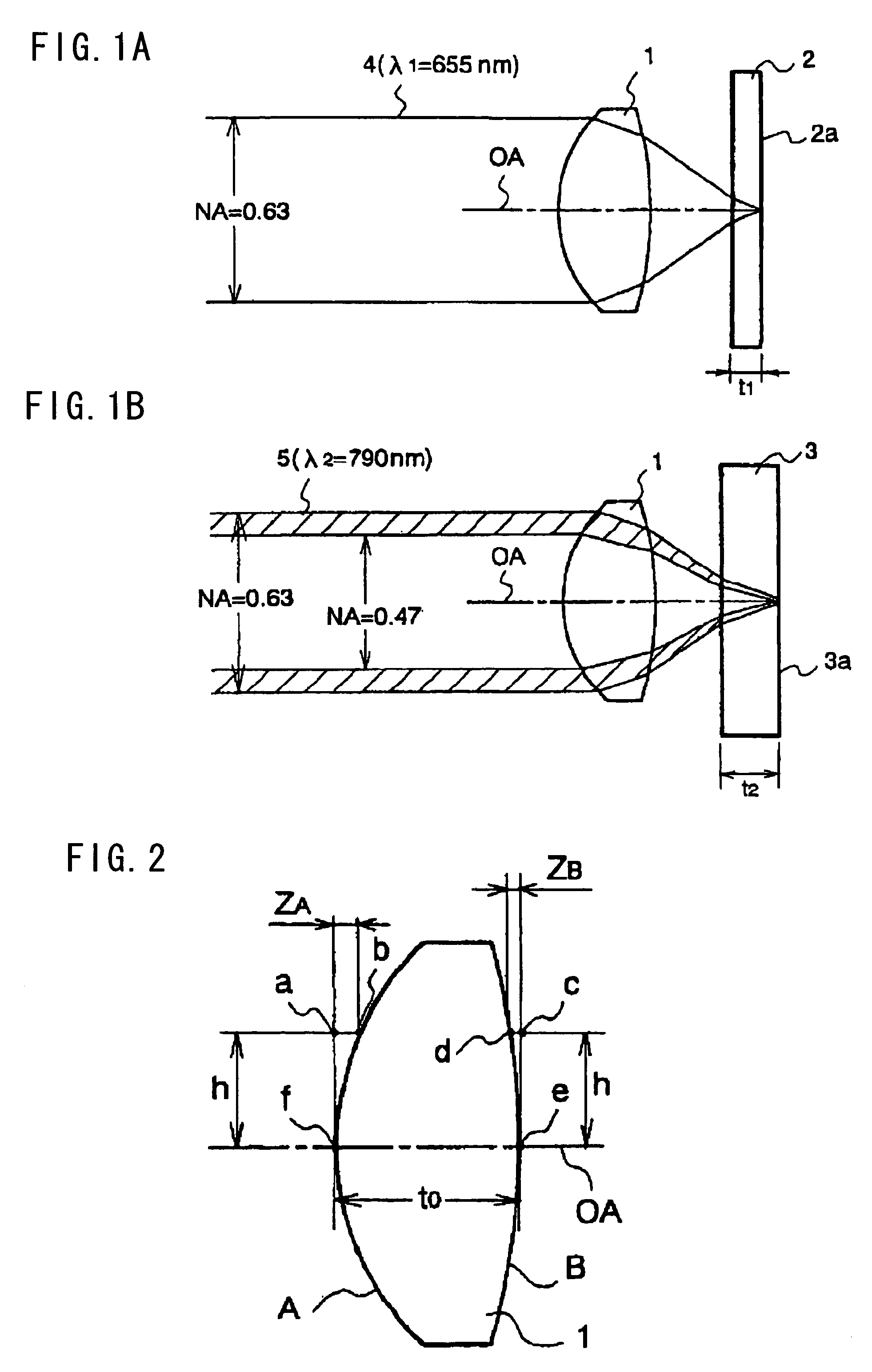
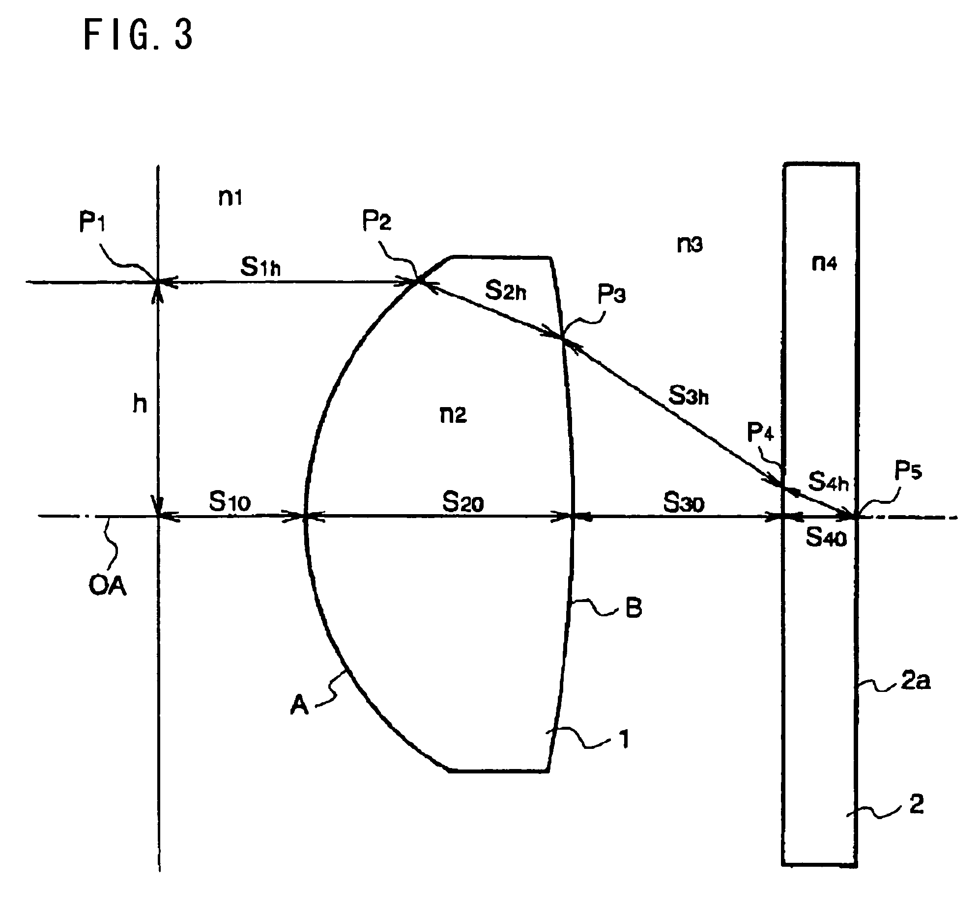
[0073]FIGS. 1A and 1B are diagrams to show an objective lens according to the present invention, and FIG. 1A is for DVD, and FIG. 1B is for CD. In FIGS. 1A and 1B, reference symbol 1 denotes an objective lens according to the present embodiment, 2 denotes a transparent substrate of a DVD (which will be hereinafter referred to as DVD substrate), 3 denotes a transparent substrate of CD (CD substrate), and 4 and 5 denote laser beams.

[0074]In FIG. 1A, the optical lens 1 is mounted in an optical head (not shown) of an optical disc apparatus. A DVD is installed in the optical disc apparatus, and the objective lens 1 condenses the laser beam 4 as a parallel light, thereby processing recording or reproducing. Here, the DVD substrate 2 has the thickness t1 of 0.6 mm, and the laser beam 4 has wavelength λ1=655 nm, being a luminous flux having numerical aperture (NA)=0.63. Under such conditions, the laser beam is condensed on the information surface 2a formed on the DVD substrate 2 on the reve...

second embodiment

[0096]Now, the objective lens according to the present invention will explained herein below.

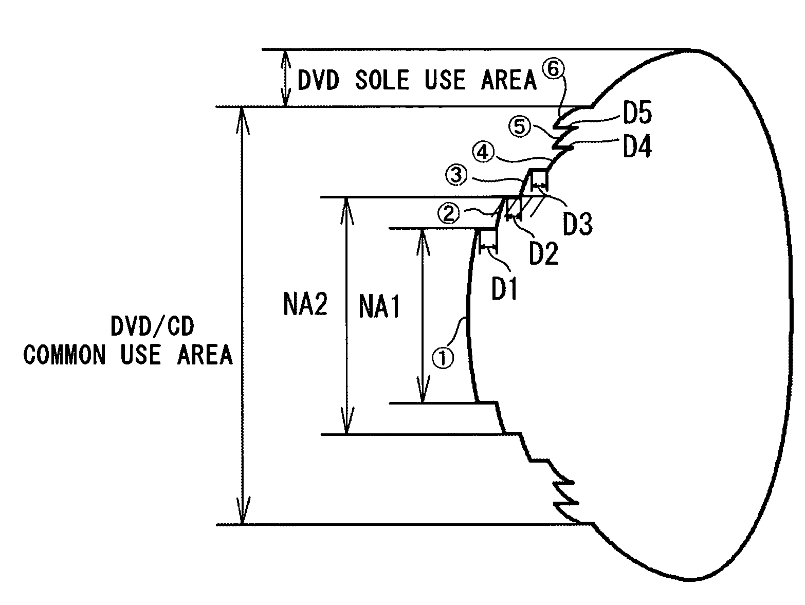
[0097]In the second embodiment whose basic structure is the same as the first embodiment, the light incident side A is radially sectioned into a plurality of zones from the optical axis, and each zone surface is configured so that the aberrations for both DVD and CD are reduced to fall within the allowable value.

[0098]The surface structure of the light incident side A according to the second embodiment will be explained hereinafter with reference to FIG. 2. The distance between the points a and b in a j-th zone from the optical axis OA in the direction of the light height h (in the radial direction) on the light incident side A is expressed by the following function ZAj

[0099]ZAj=B+C⁢⁢h21+1-(K+1)⁢⁢C2·h2+A4·h4+A6·h6+A8·h8+A10·h10+A12·h12+A14·h14+A16·h16Formula⁢⁢9

The light height h in Formula 9 is that in the j-th zone.

[0100]The following table shows the range of h and the constant B, C, K, A4...

fourth embodiment

[0167]Further, to reduce the wavefront aberration for CD in Zone 2 in addition to in Zone 1, the fourth embodiment shown in Table 8 below may be used.

[0168]

TABLE 8FOURTH EMBODIMENTZONE jhBCKA4A61    0~0.464667 04.45390E−01−6.674830.0275    1.026695   20.464667~0.687967 0.001084094.46999E−01−8.52884E−01−1.11390E−03  8.21580E−0330.687967~0.904685 0.002168184.45826E−01−5.85171E−012.36910E−03−5.00360E−03  40.904685~1.414529 0.003252264.46759E−01−6.51167E−019.59140E−044.83750E−0451.414529~1.519145 0.002168184.28660E−01−3.27869E−016.74850E−033.92010E−0461.519145~1.589366 0.001084094.42061E−01−5.75461E−012.50970E−031.75070E−0471.589366~1.847991 0.001030734.45481E−01−6.24870E−011.77360E−031.24130E−0481.847991~2.2   −0.001137444.45319E−01−6.13552E−011.64620E−031.15930E−04ZONE jA8A10A12A14A161−14.364412    106.233381   −431.806672    895.812958    −725.25403    2  9.75070E−03−3.03780E−02−4.03770E−021.80080E−01−2.00000E−013  4.59410E−03  3.04280E−03−8.16540E−036.55040E−03−2.40830E−034  2.53240...


PUM

PropertyMeasurementUnit
thicknessaaaaaaaaaa
thicknessaaaaaaaaaa
wavelengthaaaaaaaaaa

Abstract

The multi-wavelength lens for condensing a plurality of kinds of monochromatic light by refraction is disclosed. The lens comprises a common use area for all monochromatic light on at least one lens surface, the area sectioned into a plurality of aspherical zones each of which having a different refractive power; and step portions, each of which formed between adjacent aspherical zones of the plurality of aspherical zones and having a step height Dj (j=1,2,3,4, and so on, in order of closeness to a lens optical axis) in a direction parallel to the lens optical axis. At least half of the step portions satisfy a following formula when a minimum value and a maximum value of Aij for each wavelength λi are MIN(Aij) and MAX(Aij), respectively:MAX(Aij) / MIN(Aij)<3where, Aij=absolute(Bij−mij),Bij=(absolute(Dj))*(ni−1) / λi−C, ni is a refractive index of a lens for a wavelength λi, mij is an integral number closest to Bij, and C is a corrective term.

Description

CROSS-REFERENCE TO RELATED APPLICATION[0001]The present invention is related to Japanese Patent Application Serial No. 2003-273055, which is hereby incorporated.BACKGROUND OF THE INVENTION[0002]1. Field of the Invention[0003]The present invention relates to a general-purpose multi-wavelength lens used in a recording and reproducing apparatus of a multi-wavelength optical system using a plurality of kinds of monochromatic light which is compatible with optical storage medium of different types such as compact discs (CD) including CD-R, digital versatile discs (DVD), and Blue-laser-based advanced optical discs (AOD), and a multi-wavelength optical system, an optical head and an optical disc apparatus.[0004]2. Related Background Art[0005]Conventionally, compatible optical disc apparatus capable of reproducing different types of optical discs such as CD and DVD have been proposed. The CD and DVD (which will be hereinafter collectively referred to as an optical disc) have a transparent s...

Claims


Application Information

Patent Timeline
Patent Type & Authority Patents(United States)
IPC IPC(8): G02B13/02G02B13/00G11B7/00G02B3/04G02B3/10G11B7/125G11B7/1275G11B7/135G11B7/1367G11B7/1374G11B7/1392
CPCG02B3/04G02B3/10G11B7/1275G11B7/1374G11B7/13922G11B7/1367G11B2007/0006G02B13/18
Inventor SUGI, YASUYUKI
Owner MAXELL HLDG LTD
Why Eureka
Try Eureka