Extendable heat dissipation apparatus

a heat dissipation apparatus and heat dissipation area technology, applied in the direction of electrical apparatus construction details, indirect heat exchangers, lighting and heating apparatus, etc., can solve the problems of increasing heat production and accumulation, failure of devices to work, and breakdown, and achieve the effect of more flexibility in adjusting the heat dissipation area

Active Publication Date: 2008-08-12
ASUSTEK COMPUTER INC
View PDF4 Cites 21 Cited by
  • Summary
  • Abstract
  • Description
  • Claims
  • Application Information

AI Technical Summary

Benefits of technology

[0010]It is therefore an aspect of the present invention to provide an extendable heat dissipation apparatus for more flexibility of adjusting heat dissipation area for different system dimensions.
[0012]It is another aspect of the present invention to provide an extendable heat dissipation apparatus for enlarging heat dissipation area above a north bridge chip or a CPU in a computer system, and moreover, for improving convection effect by a CPU fan.
[0014]According to a preferred embodiment, an extendable heat dissipation apparatus is applied in a computer system and installed on an add-in card near a north bridge chip. The extension of the extendable heat dissipation member to the space above the north bridge chip or a CPU not only leads to a larger heat dissipation area, but obtains an advantageous convection by airflow from a CPU fan in the space; therefore heat dissipation efficiency is improved.
[0015]In conclusion, the extendable heat dissipation apparatus of the invention is applicable to various dimensions of electrical systems such as computer systems and is able to adjust heat dissipation area of the heat dissipation apparatus so that spare space within the system can be utilized fully. Especially for application in a computer system, when space above a north bridge chip is used for extension of the heat dissipation apparatus, a CPU fan also provides a heat convection for the apparatus to obtain a better heat dissipation effect.

Problems solved by technology

As electric technology grows rapidly, devices operate at higher and higher speeds and consequently produce and accumulate more and more heat.
When safe operational temperatures are surpassed, devices fail to work and may even break down.
To improve the heat dissipation efficiency, most conventional techniques enlarge the scale of the heat dissipation apparatus to increase the heat dissipative area, resulting in a specific and limited applicability.

Method used


Image

  • Extendable heat dissipation apparatus
  • Extendable heat dissipation apparatus
  • Extendable heat dissipation apparatus

Examples


Embodiment Construction

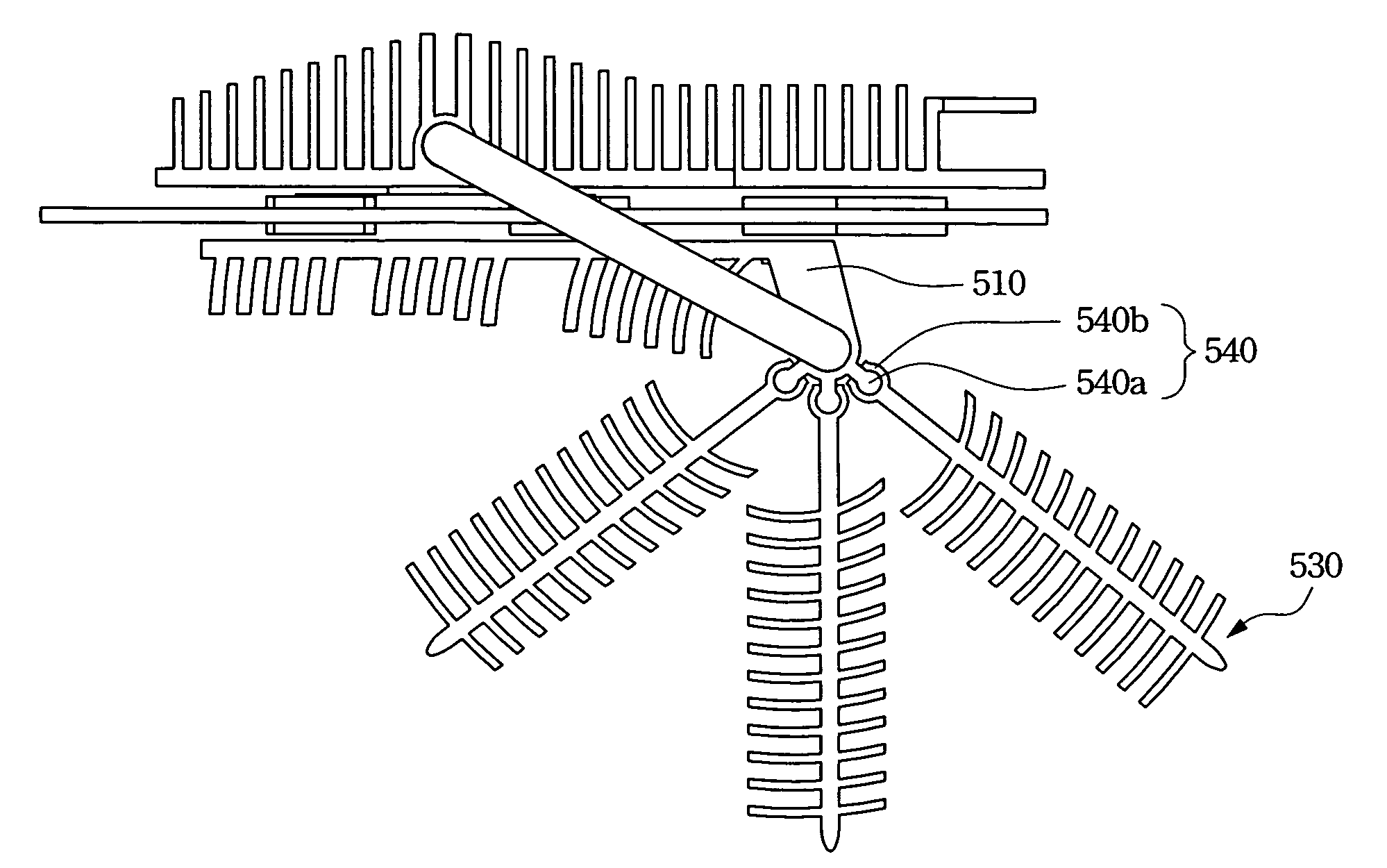
[0028]The present invention provides users with an adjusting mechanism through an extendable heat dissipation member, such that the heat dissipation apparatus can be expanded to achieve a larger heat dissipation area and a better heat dissipation efficiency according to a system volume, thus fully utilizing spare space in the system to improve heat dissipation, especially for systems with enough space.

[0029]Reference will now be made in detail to the present preferred embodiments of the invention, examples of which are illustrated in the accompanying drawings. Wherever possible, the same reference numbers are used in the drawings and the description to refer to the same or like parts.

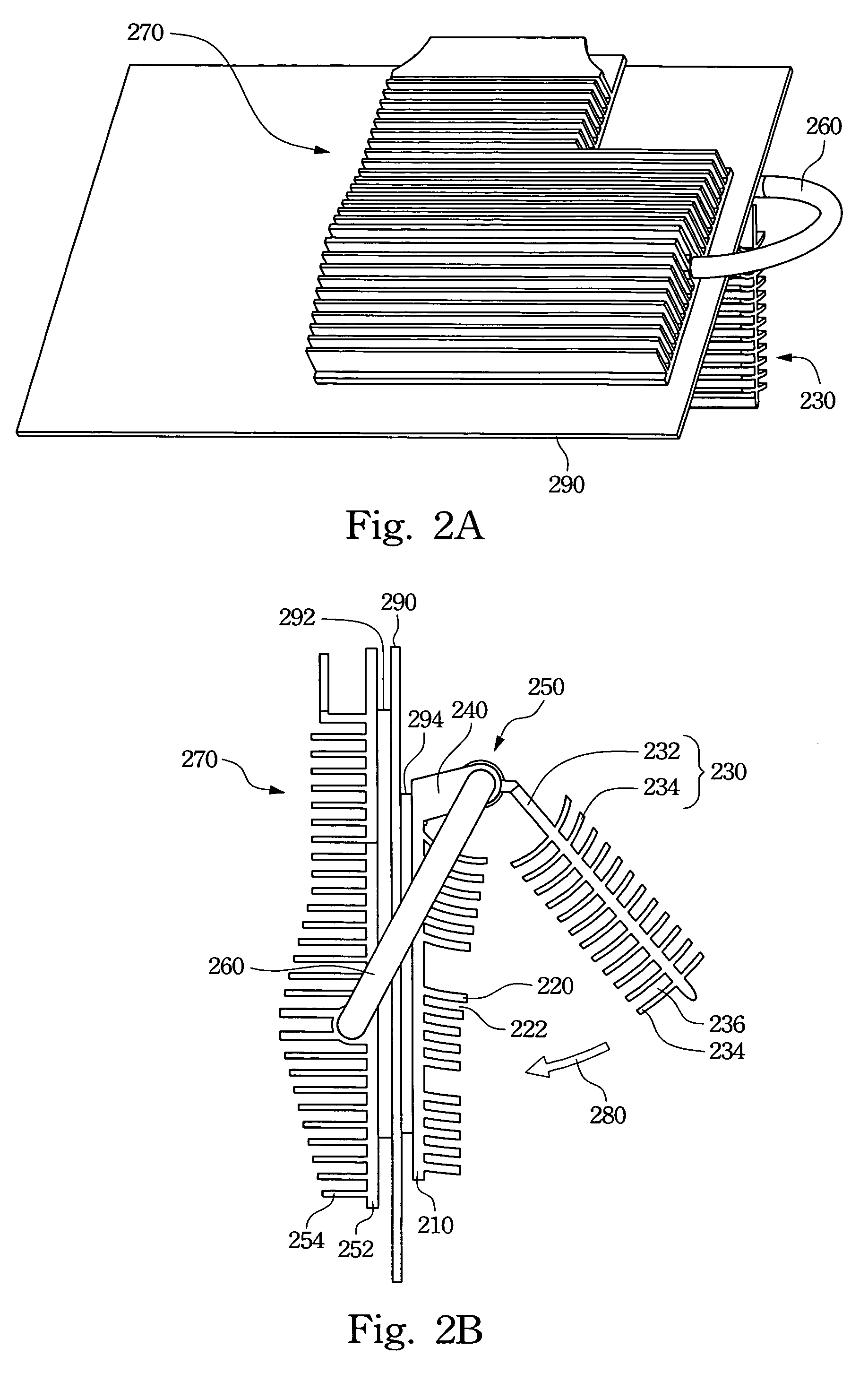
[0030]FIGS. 2A and 2B are respectively an oblique view and a side view of an extendable heat dissipation apparatus in accordance with a preferred embodiment of the present invention. The extendable heat dissipation apparatus 250 includes a base 210, an extendable heat dissipation member 230, and a conne...


PUM


Abstract

An extendable heat dissipation apparatus includes a base, an extendable heat dissipation member and a connecting element. A normal fin is formed on the base, and the connecting element integrates the extendable heat dissipation member in the apparatus with the base. The extendable heat dissipation member can be extendable to an extending location and can also be stored in a storing location with respect to the base.

Description

RELATED APPLICATIONS[0001]The present application is based on, and claims priority from, Taiwan Application Serial Number 94123269, filed Jul. 8, 2005, the disclosure of which is hereby incorporated by reference herein in its entirety.BACKGROUND[0002]1. Field of Invention[0003]The present invention relates to a heat dissipation apparatus. More particularly, the present invention relates to a heat dissipation apparatus which can extend to increase heat dissipation area.[0004]2. Description of Related Art[0005]As electric technology grows rapidly, devices operate at higher and higher speeds and consequently produce and accumulate more and more heat. When safe operational temperatures are surpassed, devices fail to work and may even break down.[0006]A conventional heat dissipation technique is to attach a heat dissipation apparatus 100 to an electrical device such as a chip, as shown in FIG. 1, and even to mount a fan on the heat dissipation apparatus 100. A heat pipe may also be used ...

Claims


Application Information

Patent Timeline
Patent Type & Authority Patents(United States)
IPC IPC(8): H05K7/20H01L23/36
CPCF28D15/0266F28F1/20F28F1/30H01L23/427H01L23/467F28F2280/10H01L2924/0002F28F2215/14F28F2215/10H01L2924/00
Inventor CHANG, CHIEN-LUNGLI, FEN-YINGHUANG, KUO-HSUN
Owner ASUSTEK COMPUTER INC
Why Eureka
Try Eureka