Deflected drop liquid pattern deposition apparatus and methods

a drop pattern and liquid pattern technology, applied in printing and other directions, can solve the problems of difficult difficult manufacturing and accurate control of the system, and small physical separation or discrimination between the two drop paths

Inactive Publication Date: 2008-08-19
EASTMAN KODAK CO
View PDF14 Cites 15 Cited by
  • Summary
  • Abstract
  • Description
  • Claims
  • Application Information

AI Technical Summary

Problems solved by technology

While serviceable, these electrostatic deflection printheads are difficult to manufacture at low cost and suffer many reliability problems do to shorting and fouling of the drop charging electrodes and deflection electric field plates.
The physical separation or amount of discrimination between the two drop paths is very small and difficult to control.
Such a system is difficult to manufacture and accurately control.
The physical separation or amount of discrimination between the two drop paths is erratic due to the uncertainty in the increase and decrease of air flow during switching resulting in poor drop trajectory control and imprecise drop placement.
Pneumatic operation requiring the air flows to be turned on and off is necessarily slow in that an inordinate amount of time is needed to perform the mechanical actuation as well as time associated with the settling any transients in the air flow.
Further, it would be costly to manufacture a closely spaced array of uniform first pneumatic deflectors necessary to extend the Taylor '844 concept to a plurality of closely spaced jets.
While workable, this apparatus tends to produce large anomalous swings in the amount of stream deflection as the surface properties are affected by contact with the working fluid.
This approach is workable however the apparatus prone to electrical breakdown due to a build up-of conductive debris around the deflection electrodes.
This approach is workable however the printhead structure is more complex to fabricate and it is difficult to achieve uniform deflection from all of the jets in a large array of jets.
While the ink jet printer disclosed in Chwalek '821 works extremely well for its intended purpose, the amount of physical separation between printed and non-printed liquid drops is limited which may limit the robustness of such a system.
Simply increasing the amount of asymmetric heating to increase this separation will result in higher temperatures that may decrease reliability.
However, to be effective, the apparatus of Chwalek '921 requires a substantial difference in large and small drop volumes which has the effect reducing printing speed as time and liquid volume is spent creating large drops.
Different drop sequences with be differently deflected, resulting in the addition of data dependent drop placement error for the printed drops.
Further, the approach of Sharma '542 may be unsuitable to implement for a large array of jets as it is difficult to achieve sufficiently uniform gas flow behavior along a wide slit source so that the point of transition to incoherent gas flow would occur at the same distance from the nozzle for all jets of the array.

Method used


Image

  • Deflected drop liquid pattern deposition apparatus and methods
  • Deflected drop liquid pattern deposition apparatus and methods
  • Deflected drop liquid pattern deposition apparatus and methods

Examples


Embodiment Construction

[0044]The present description will be directed in particular to elements forming part of, or cooperating more directly with, apparatus in accordance with the present invention. Functional elements and features have been given the same numerical labels in the figures if they are the same element or perform the same function for purposes of understanding the present inventions. It is to be understood that elements not specifically shown or described may take various forms well known to those skilled in the art.

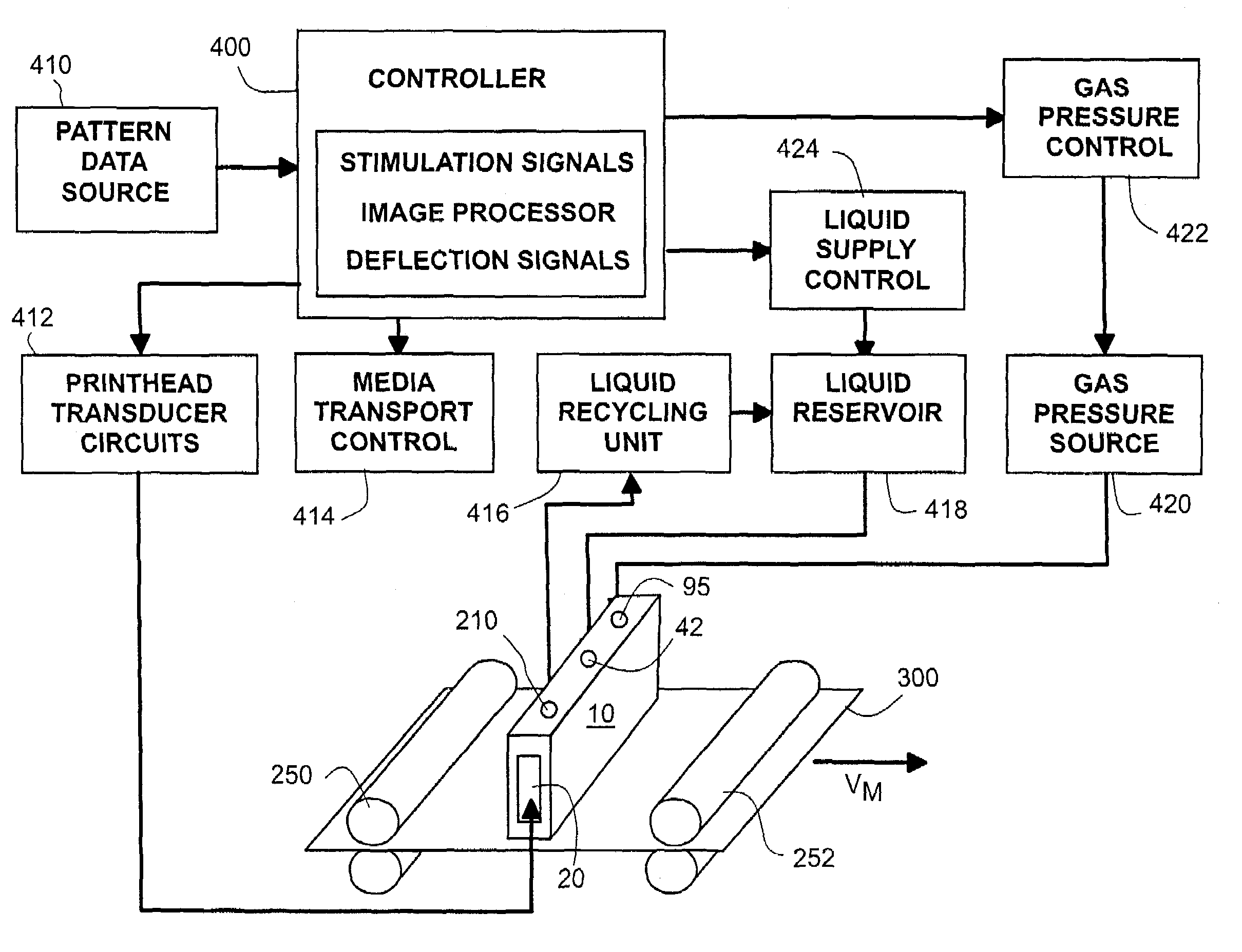
[0045]Referring to FIG. 1, a continuous drop emission system for depositing a liquid pattern is illustrated. Typically such systems are ink jet printers and the liquid pattern is an image printed on a receiver sheet or web. However, other liquid patterns may be deposited by the system illustrated including, for example, masking and chemical initiator layers for manufacturing processes. For the purposes of understanding the present inventions the terms “liquid” and “ink” will be ...


PUM


Abstract

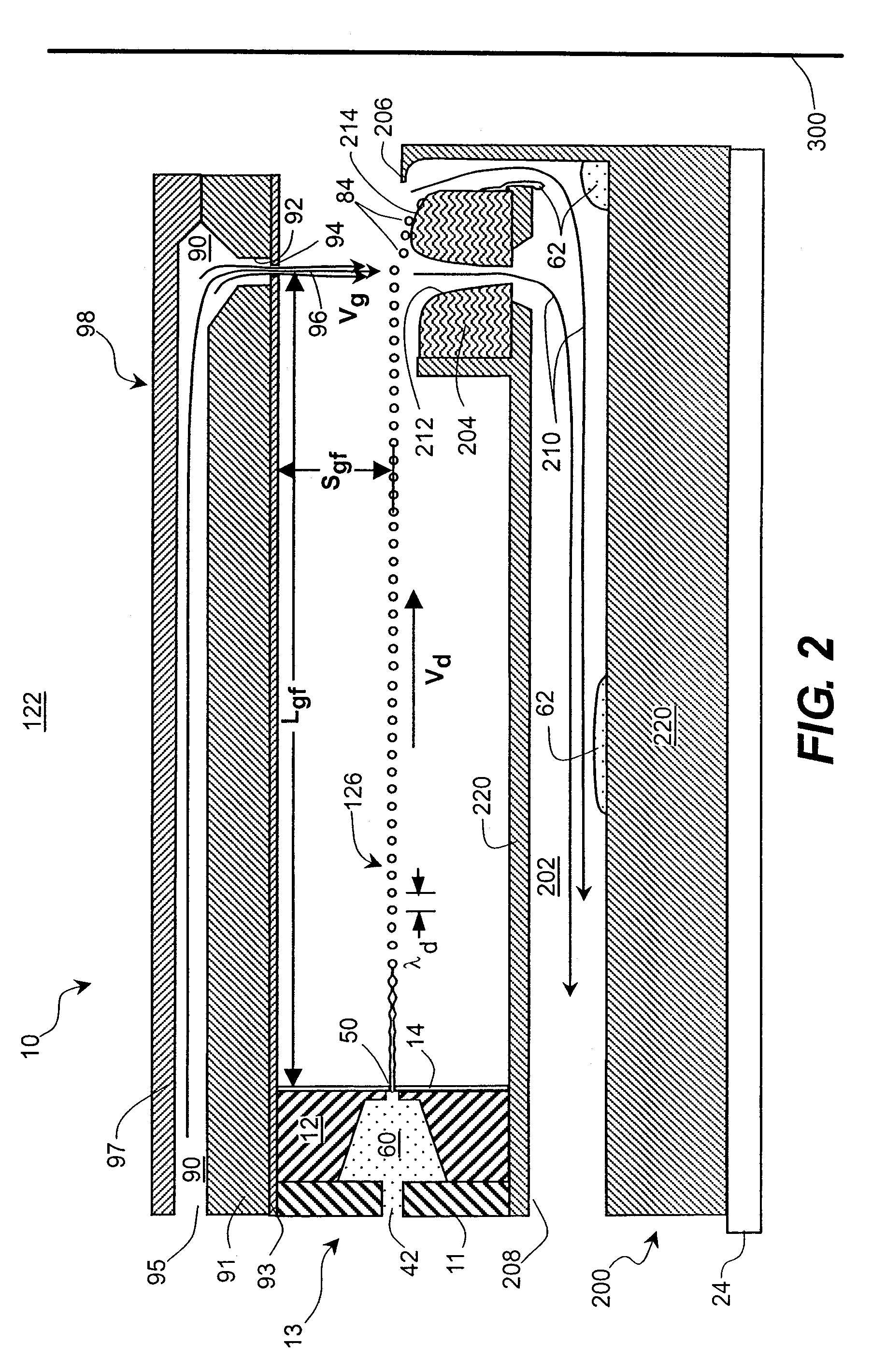
Drop deflector apparatus and methods for a continuous drop emission system comprising a plurality of drop nozzles emitting a plurality of continuous streams of a liquid that break up into streams of drops of substantially uniform drop volume having nominal flight paths that are substantially within a nominal flight plane are disclosed. A plurality of path selection elements corresponding to the plurality of continuous streams of drops is provided operable to firstly deflect individual drops from the corresponding continuous stream of drops along a first deflection flight path diverging from the nominal flight path based on pattern data. A plurality of gas nozzles is provided which generate a plurality of localized gas flows, positioned along one of the first deflection flight paths or the nominal flight paths, wherein the localized gas flows are oriented so as to cause a substantial second deflection of one of the firstly deflected drops or the nominal drops in a direction perpendicular to the nominal flight plane without causing a substantial deflection of drops following the other of the first deflection flight paths or the nominal flight paths. Secondly deflected drops are captured before they impinge a receiver medium. An image pattern is thereby deposited by either firstly deflected or undeflected drops.

Description

FIELD OF THE INVENTION[0001]This invention relates generally to the field of digitally controlled printing and liquid patterning devices, and in particular to continuous ink jet systems in which a liquid stream breaks into drops, some of which are selectively deflected.BACKGROUND OF THE INVENTION[0002]Traditionally, digitally controlled liquid patterning capability is accomplished by one of two technologies. In each technology, a patterning liquid is fed through channels formed in a printhead. Each channel includes a nozzle from which drops of liquid are selectively extruded and deposited upon a medium. When color marking is desired, each technology typically requires independent liquid supplies and separate liquid delivery systems for each liquid color used during printing.[0003]The first technology, commonly referred to as “drop-on-demand” ink jet printing, provides liquid drops for impact upon a recording surface using a pressurization actuator (thermal, piezoelectric, etc.). Sel...

Claims


Application Information

Patent Timeline
Patent Type & Authority Patents(United States)
IPC IPC(8): B41J2/09
CPCB41J2/03B41J2/09B41J2002/032B41J2002/031B41J2002/022
Inventor JEANMAIRE, DAVID L.
Owner EASTMAN KODAK CO
Why Eureka
Try Eureka