
Electromagnetic interference filter

a technology of electromagnetic interference and filter, applied in the direction of transformer/inductance magnetic core, emergency protective arrangement for limiting excess voltage/current, core/yokes, etc., can solve the problems of increased cost of electrical devices, noise in ac current comprising differential mode, and electromagnetic interference (emi). , to achieve the effect of simplifying manufacturing and reducing circuit cos

Inactive Publication Date: 2008-08-19
DELTA ELECTRONICS INC
View PDF7 Cites 7 Cited by
  • Summary
  • Abstract
  • Description
  • Claims
  • Application Information

AI Technical Summary

Benefits of technology

[0007]Accordingly, the invention discloses an electromagnetic interference (EMI) filter for common mode noise and differential mode noise, which not only reduces cost of the circuit but also simplifies the manufacturing.

Problems solved by technology

When alternating current (AC) power is employed, parasitic capacitance or stray capacitance may occur in the power supply or the high-frequency converter, and noise of stray current in the AC current, leading to electromagnetic interference (EMI).
Generally, noise in the AC current comprises differential mode noise and common mode noise.
As a result, cost of the electrical device is increased, and manufacturing thereof complicated.

Method used


Image

  • Electromagnetic interference filter
  • Electromagnetic interference filter
  • Electromagnetic interference filter

Examples


first embodiment

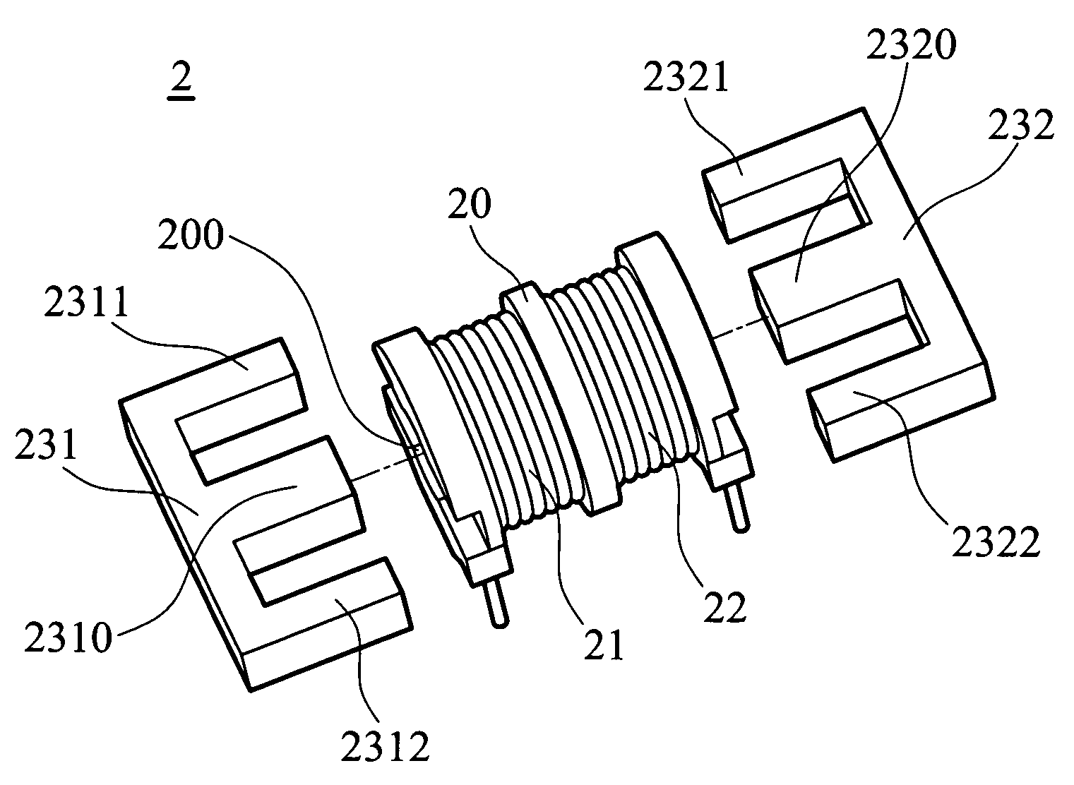
[0037]FIG. 5 shows a perspective dissembled view of the EMI filter 2 of the The first wire 21 and the second wire 22 are wound around the first magnetomotive element 20 respectively, and the first magnetomotive element 20 can be an iron core pressed by iron powder or a ferrite core pressed and sintered by ferrite powder. The first magnetomotive element 20 has a through hole 200, which axially penetrates the first magnetomotive element 20. Referring to FIG. 6, the first magnetomotive element 20 comprises a first bobbin portion 201 wound by the first wire 21 and a second bobbin portion 202 wound by the second wire 22. Preferably, the first bobbin portion 201 and the second bobbin portion 202 can be respectively ring-shaped concaves depressed on the first magnetomotive element 20 and surrounding the through hole 200. However, the first bobbin portion 201 and the second bobbin portion 202 are not limited thereto and can be disposed on the surface of the first magnetomotive element 20 i...

second embodiment

[0043]Accordingly, the second magnetomotive element 43 of the EMI filter 4 can be formed by two U-shaped magnetomotive blocks. Referring to FIG. 11, the first block 431 and the second block 432 can be respective U-shaped magnetomotive blocks and are mirrored-disposed. A first column 4310 of the first block 431 and a second column 4320 of the second block 432 penetrate the through hole 400 relatively, and the first column 4310 of the first block 431 and the second column 4320 of the second block 432 form the first portion 51 of the second magnetomotive element 43 in FIG. 10. The other column (i.e. a third column 4311 of the first block 431 and the other column (i.e. a third column 4321) of the second block 432 are disposed relatively opposite to each other, forming a second portion 51 as shown in FIG. 10. Thus, the second magnetomotive element 43 forms an O-shaped closed magnetic loop, and the EMI filter 4 filters differential mode noise. Another embodiment of the second magnetomotiv...


PUM


Abstract

An electromagnetic interference (EMI) filter includes a first magnetomotive element, a first wire, a second wire, and a second magnetomotive element. The second magnetomotive element forms a closed magnetic loop, which comprises a first portion penetrating a through hole of the first magnetomotive element. Thus, the first wire and the second wire in the Filter filter not only differential mode noise but also common mode noise.

Description

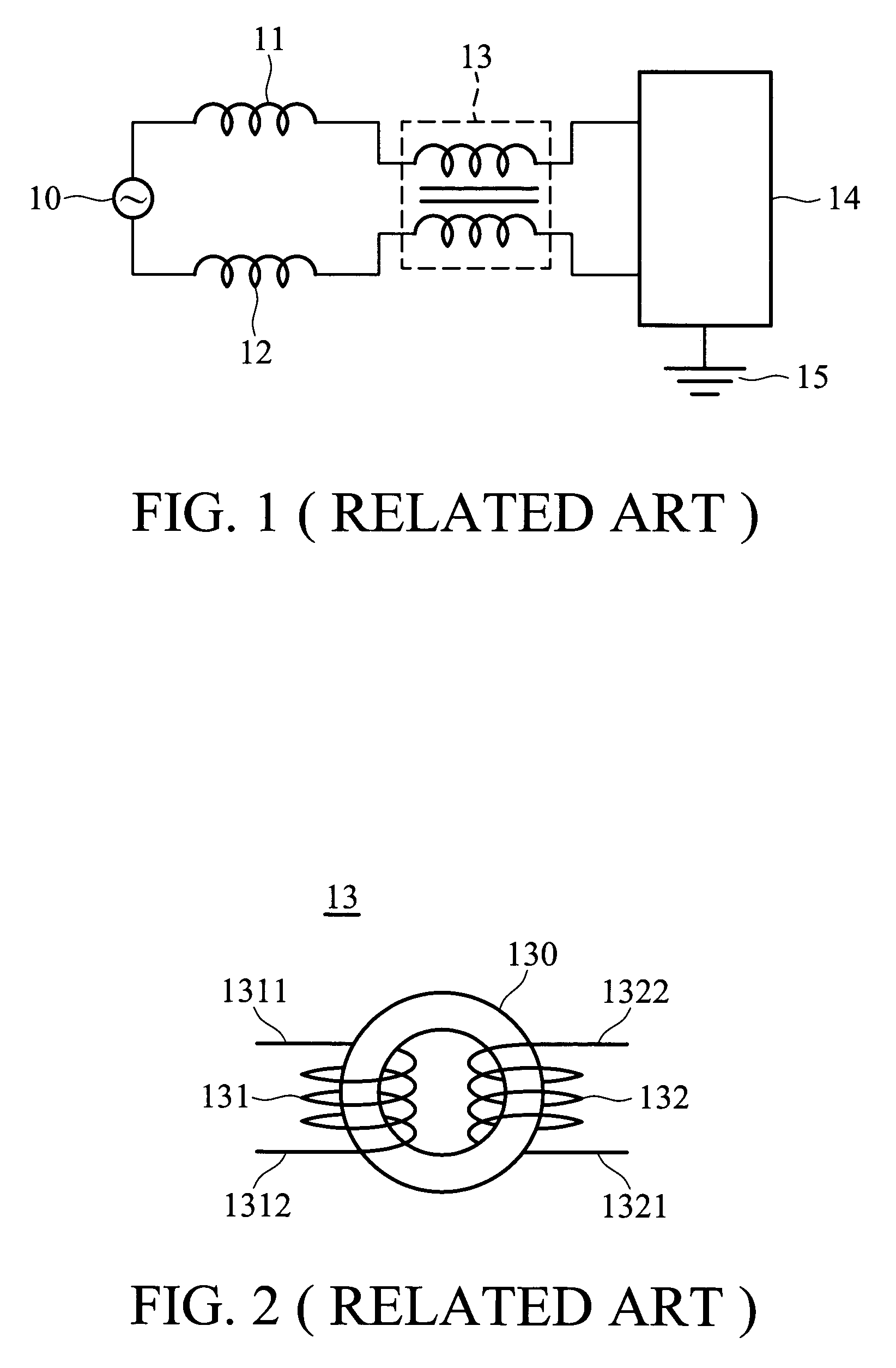
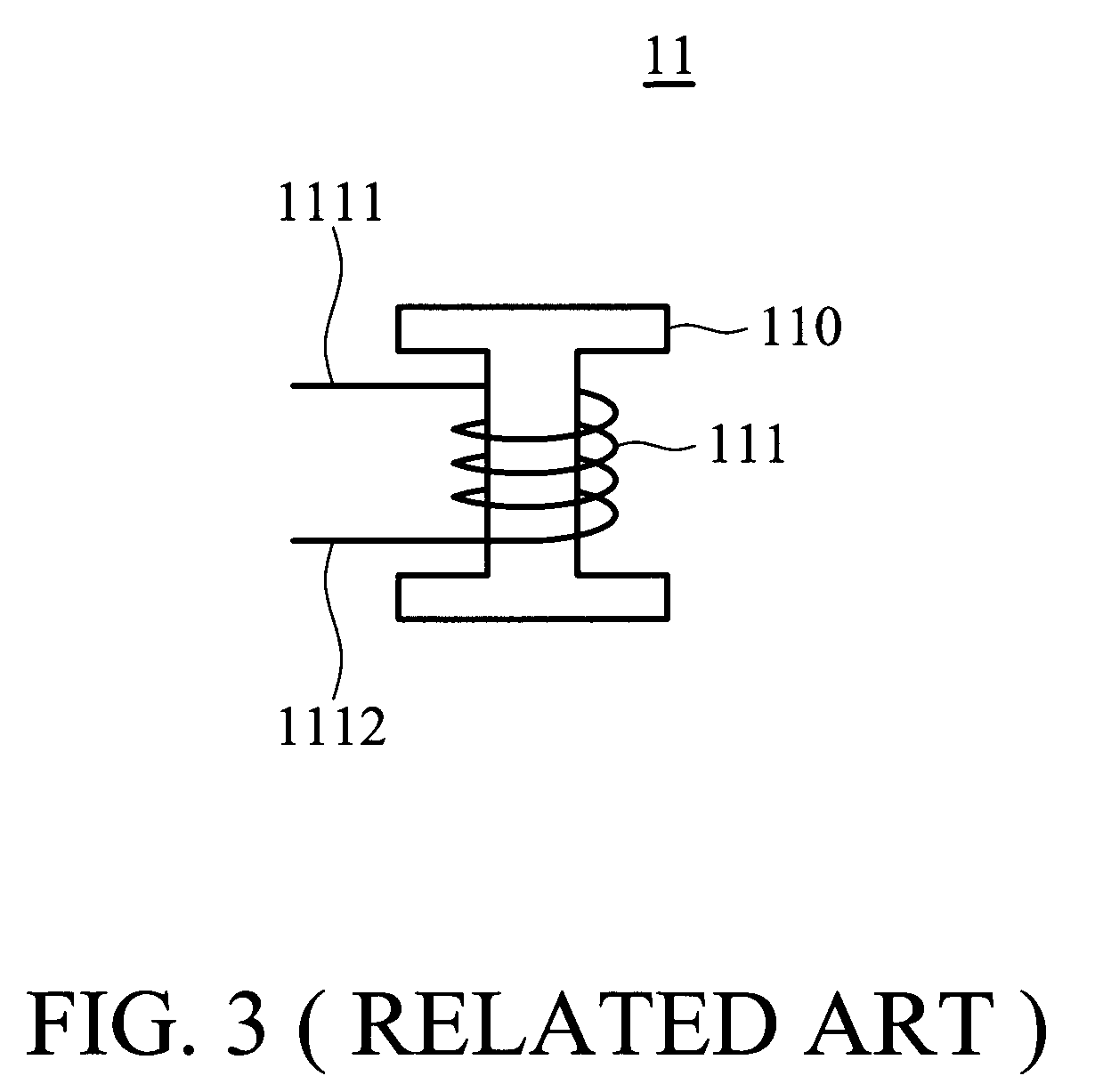
BACKGROUND OF THE INVENTION[0001]1. Field of the Invention[0002]The invention relates to electromagnetic interference (EMI) filters, and particularly to an EMI filter suitable for filtering common mode noise and differential mode noise.[0003]2. Brief Discussion of the Related Art[0004]Presently, electronic devices are frequently used in daily life, and power is required for operation thereof. When alternating current (AC) power is employed, parasitic capacitance or stray capacitance may occur in the power supply or the high-frequency converter, and noise of stray current in the AC current, leading to electromagnetic interference (EMI).[0005]Generally, noise in the AC current comprises differential mode noise and common mode noise. There are several conventional circuit compositions for filtering the noise. One conventional circuit composition is shown in FIG. 1, in which an AC power supply 10 is connected to a first differential mode EMI filter 11 and a second differential mode EMI ...

Claims


Application Information

Patent Timeline
IPC IPC(8): H01F27/24
CPCH01F17/04H01F27/255H01F3/10H03H2001/005H01F27/306H01F2017/065
Inventor WU, CHEN-FENGCHOU, HENG-CHENG
Owner DELTA ELECTRONICS INC
Learn More