Method and system for proximity detection for an in-building wireless repeater

a wireless repeater and proximity detection technology, applied in transmission monitoring, frequency-division multiplex, high-level techniques, etc., can solve problems such as attenuation or otherwise degrading signals passing over the air interface, cellular wireless communications can suffer from varying levels of signal degradation, and problems that can be even more acute, so as to achieve the effect of higher power

Active Publication Date: 2008-08-19
SPRINT SPECTRUM LLC
View PDF22 Cites 165 Cited by
  • Summary
  • Abstract
  • Description
  • Claims
  • Application Information

AI Technical Summary

Problems solved by technology

Unfortunately, however, cellular wireless communications can suffer from varying levels of signal degradation as signals are carried over the air interface between the wireless devices and the base station.
Further, obstructions such as buildings and foliage can attenuate or otherwise degrade signals passing over the air interface.
When a wireless device operates within a building, the problem can be even more acute, as the structure of the building can further diminish the signal.
In a worst case scenario, forward link signals that ultimately arrive at a wireless device within a building may be too weak to be detected and / or used by the wireless device.
As a result, service could be unavailable and wireless communications could be blocked or dropped.
This is clearly a problem for cellular wireless carriers who are seeking to promote in-building use of their services.
A disadvantage with this approach, however, is that the increased power can lead to increased interference in adjacent cells.
This, in turn, can decrease the capacity of the wireless network.
The power increase can also interfere with other wireless devices in use around the base station.
The magnitude of the power increase proportionally affects the amount of interference produced by the base station, with a greater power increase causing a greater interference.
Also, this approach would only solve half the problem.
It would not aid the base station in receiving signals from a wireless device.
A disadvantage to this approach, however, is that the repeaters remain active regardless of whether any wireless devices are in range of the repeaters.
In addition to needlessly broadcasting signals that would not then be received by any wireless device, the repeaters would continue to consume power and other wireless network resources.
Although the repeaters might be deactivated or placed in a standby mode, they might not then be readily available when a wireless device moves within range.

Method used


Image

  • Method and system for proximity detection for an in-building wireless repeater
  • Method and system for proximity detection for an in-building wireless repeater
  • Method and system for proximity detection for an in-building wireless repeater

Examples


Embodiment Construction

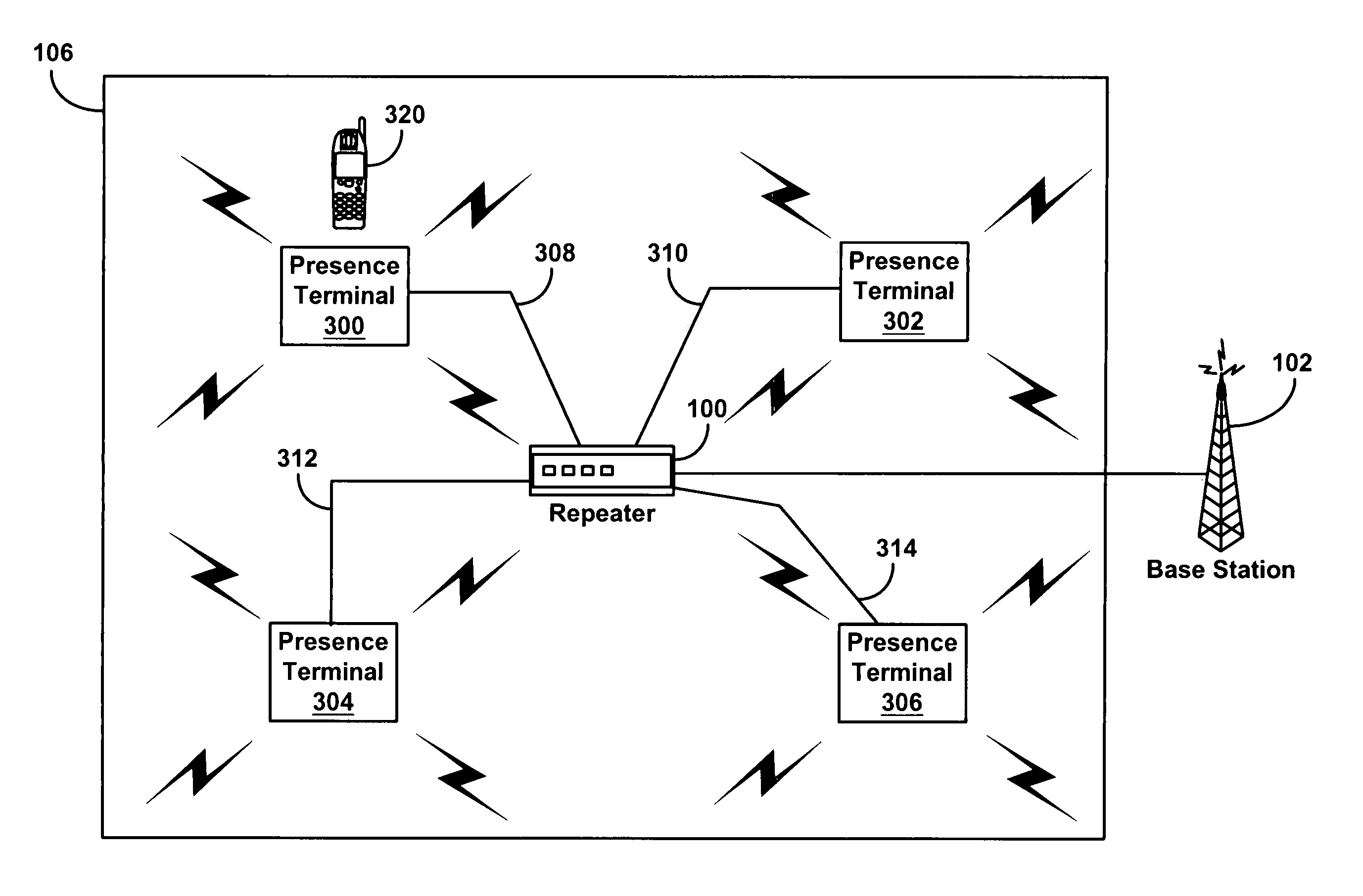
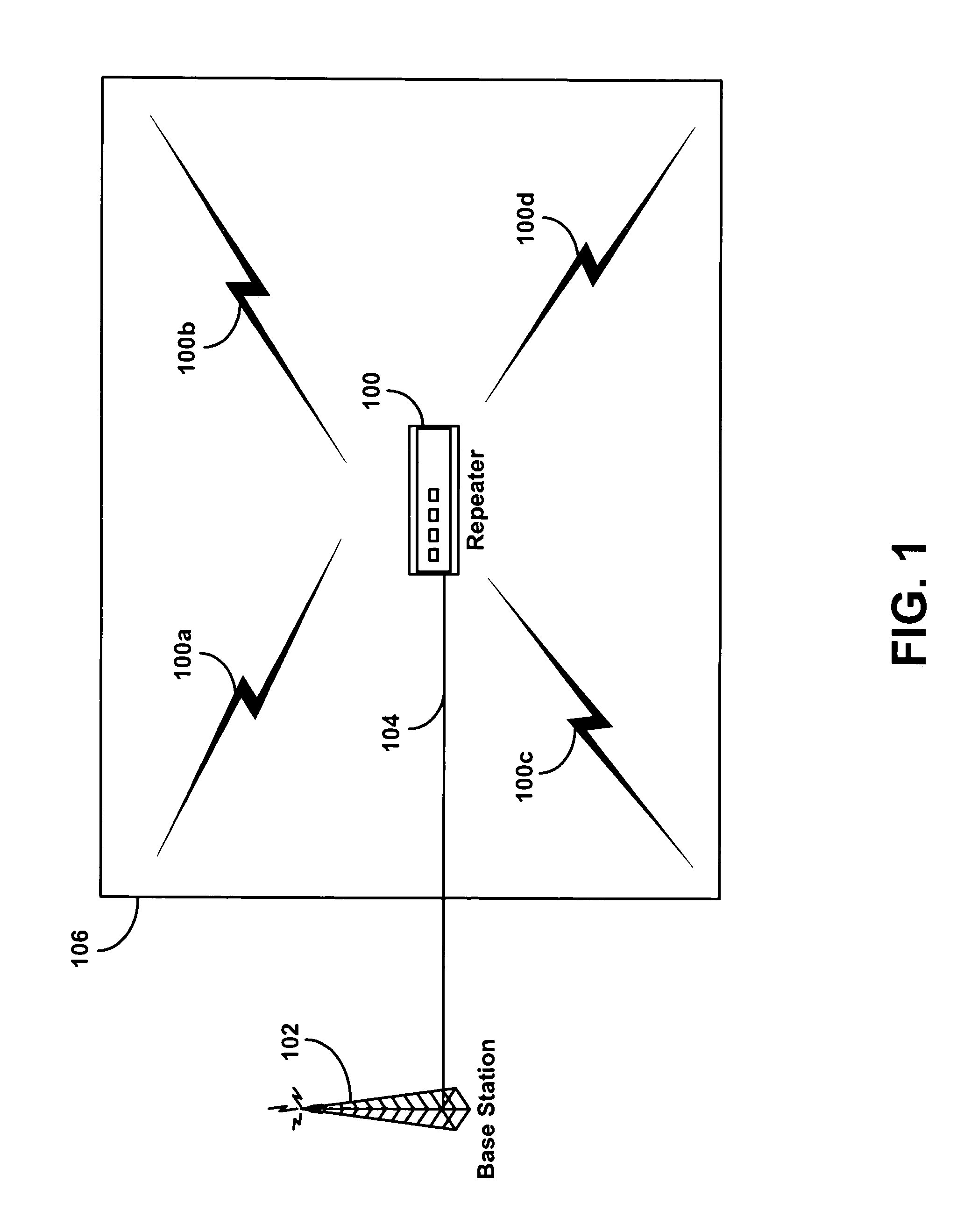
[0026]FIG. 1 is block diagram of an exemplary wireless network configuration that uses a repeater having proximity detection in order to switch the repeater between active and standby modes. A repeater 100 may connect to a base station 102 for a wireless network via wired data link 104. The base station 102 is merely exemplary in nature, however, and it is not necessary that the repeater connects to a base station 102. The particular network element that connects to the repeater might vary depending on the type and configuration of the wireless network. Also, the repeater 100 might communicate with the base station 102 or other network element through a wireless data link instead of the wired data link 104.

[0027]The repeater 100 generally functions to repeat signals sent to and from wireless devices on the wireless network. For example, the repeater 100 can receive signals that are transmitted from wireless devices. The repeater 100 can then send the signals through the wired data l...


PUM


Abstract

A repeater for a wireless network might use a first communication interface to detect the presence of a wireless device. Alternatively, another network element might use the first communication interface to detect the presence of the wireless device and then provide a notification to the repeater. The first communication interface might be a low-power communication interface, such as one that uses Bluetooth. In response to detecting a wireless device or receiving a notification, the repeater might switch to an active mode and begin repeating signals on the wireless network via a second communication interface, such as one that uses CDMA.

Description

FIELD OF THE INVENTION[0001]The present invention relates to wireless communications. More specifically, it relates to a method and system for proximity detection for a wireless in-building repeater.BACKGROUND OF THE INVENTION[0002]Cellular wireless is an increasingly popular means of personal communication in the modern world. People are using cellular wireless networks for the exchange of voice and data over wireless devices, such as cellular telephones, personal digital assistants (“PDAs”), cellular telephone modems and other devices. In principle, a user can seek information over the Internet or call anyone over a public switched telephone network (“PSTN”) from any place inside the coverage area of the cellular wireless network.[0003]In a typical cellular wireless system, an area is divided geographically into a number of cell cites, each defined by a radio frequency (“RF”) radiation pattern from a respective base transceiver station (“BTS”) antenna. The base station antennae in...

Claims


Application Information

Patent Timeline
Patent Type & Authority Patents(United States)
IPC IPC(8): H04B7/15
CPCH04B7/15557H04W16/26H04B7/2606H04W8/005Y02D30/70
Inventor NGAN, JOHN CHEONG WAI
Owner SPRINT SPECTRUM LLC
Why Eureka
Try Eureka