
Method for the spatial mapping of functional brain electrical activity

a functional brain and electrical activity technology, applied in the field of brain electrical activity monitoring and evaluation, can solve the problems of inability to determine local coherence between brain regions or spatially spaced neuron sites, and inability to accurately predict the electrical activity of brain regions. achieve the effect of reducing residual volume conduction error

Inactive Publication Date: 2008-08-19
THE TRUSTEES OF COLUMBIA UNIV IN THE CITY OF NEW YORK
View PDF8 Cites 4 Cited by
  • Summary
  • Abstract
  • Description
  • Claims
  • Application Information

AI Technical Summary

Benefits of technology

This approach enables more sensitive and accurate quantification of local synchrony, overcoming the limitations of adult EEG measurements by minimizing volume conduction artifacts, thus providing a clearer indication of neural activity and connectivity.

Problems solved by technology

Determining local coherence between brain regions or spatially spaced neuron sites, however, has been impractical.
Using EEG to determine local synchrony, however, is fraught with difficulty.
However, if the electrodes are closely spaced, as would be necessary to attempt to obtain EEG information from which local synchrony information might be obtained, volume conduction artifact due to the presence of the skull produces a spatial blurring of electrical variation.
Reasons for this include the thickness of the adult skull and its poor electrical conductivity.
As such, the measured adult EEG information is itself insufficient to allow determination of local synchrony.
However, these global neural synchrony measurements do not provide insight into the functional behavior of localized groups of activated neurons.
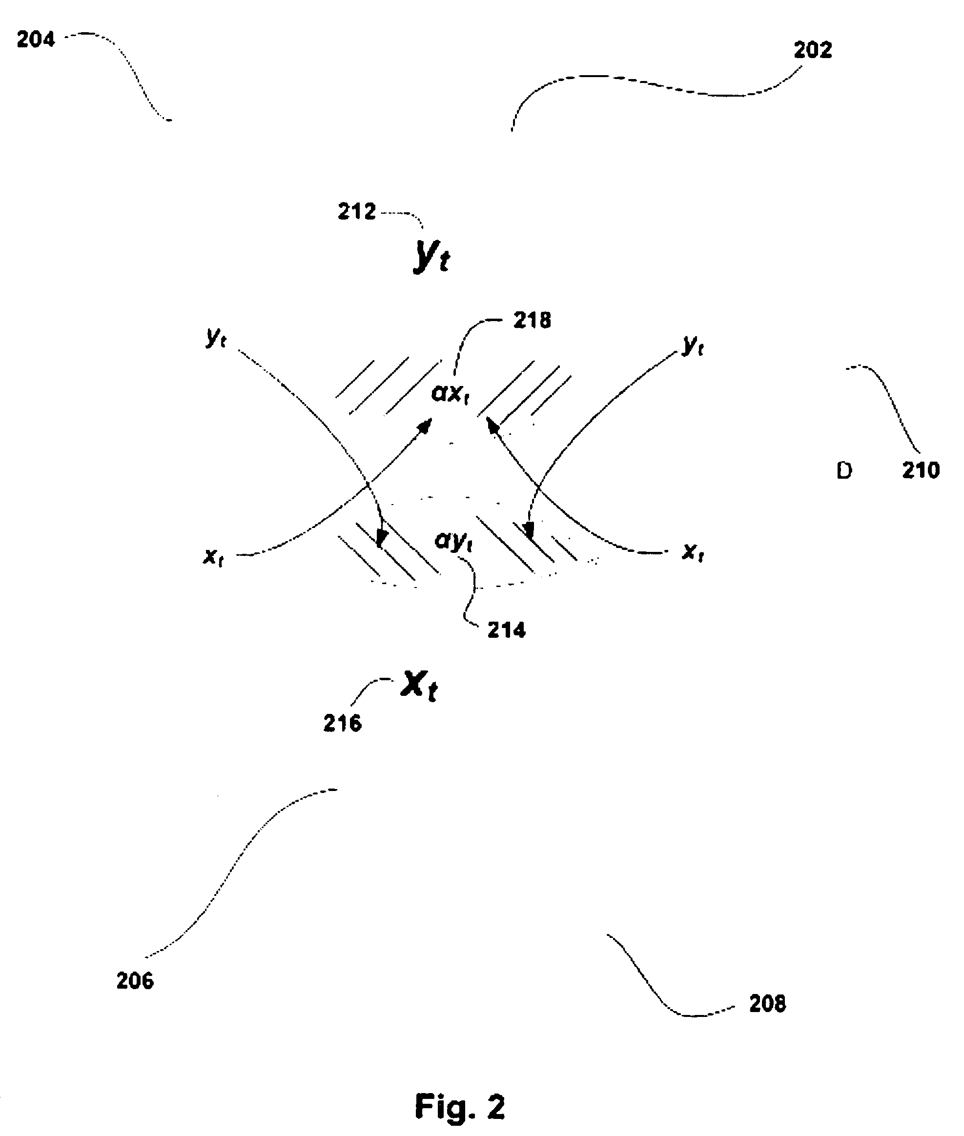
Although it would appear straightforward to calculate local synchrony from EEG data, the volume conduction of current from cortical neurons to the scalp makes the accurate measurement of synchrony difficult when the EEG is measured from closely spaced leads as is required for local synchrony.
The major cause of volume conduction is the poorly conducting skull which produces a spatial blurring of cortical electrical potential variation when measured with the scalp EEG.
This result is largely caused by volume conduction contamination of the synchrony measurements.

Method used


Image

  • Method for the spatial mapping of functional brain electrical activity
  • Method for the spatial mapping of functional brain electrical activity
  • Method for the spatial mapping of functional brain electrical activity

Examples


Embodiment Construction

[0044]In the following description of the preferred embodiments, reference is made to the accompanying drawings that form a part hereof, and in which is shown by way of illustration a specific embodiment in which the invention may be practiced. It is to be understood that other embodiments may be utilized and structural changes may be made without departing from the scope of the present invention.

[0045]The following article discuss EGG techniques, and each is hereby incorporated herein by reference in its entirety: “Quantitative Analysis of Spatial Sampling Error in the Infant and Adult Electroencephalogram,” by Philip G. Grieve, Ronald Emerson, Joseph R. Isler and Raysmond I. Stark, Neuroimage 21(4) (2004):1260-74, received 22 May 2003, revised 22 Nov. 2003, accepted 25 Nov. 2003.

[0046]In some embodiments, methods and systems of the present invention include obtaining local synchrony information. “Local synchrony information,” as used herein, includes information that provides a qu...


PUM


Abstract

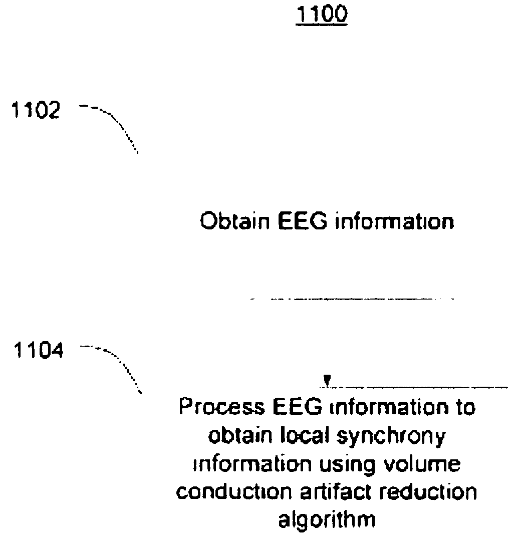
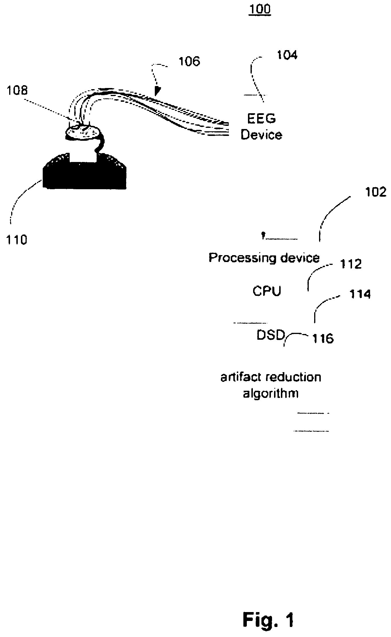
The present invention discloses methods and systems for monitoring and evaluating brain electrical activity. Methods are provided for obtaining local synchrony information relating to regions of a brain. Methods are provided that include obtaining EEG information from an infant subject, and using the obtained EEG information in obtaining local coherence information. A mathematical technique or computer algorithm can be used to process the EEG information in order to reduce residual volume conduction error in the obtained local coherence information.

Description

STATEMENT REGARDING FEDERALLY SPONSORED RESEARCH OR DEVELOPMENT[0001]This invention was made with government support under grant number EB000264 awarded by the National Institutes of Health. The government has certain rights in the invention.COPYRIGHT NOTICE[0002]A portion of the disclosure of this patent document contains material which is subject to copyright protection. The copyright owner has no objection to the facsimile reproduction by anyone of the patent document or the patent disclosure, as it appears in the Patent and Trademark Office patent files or records, but otherwise reserves all copyright rights whatsoever.BACKGROUND OF THE INVENTION[0003]This invention relates in general to monitoring and evaluating brain electrical activity, and in particular includes methods and systems for methods for monitoring and evaluating local synchrony between adjacent or neighboring brain regions or neural sites.[0004]EEG, or electroencephalogram, is used to provide a measure of brain el...

Claims


Application Information

Patent Timeline
Patent Type & Authority Patents(United States)
IPC IPC(8): A61B5/04
CPCA61B5/0476A61B5/369A61B5/372
Inventor GRIEVE, PHILIPSTARK, RAYMOND I.ISLER, JOSEPH R.
Owner THE TRUSTEES OF COLUMBIA UNIV IN THE CITY OF NEW YORK
Learn More