Vehicle steering apparatus and vehicle steering method

a technology for steering apparatuses and vehicles, applied in the direction of braking systems, braking components, transportation and packaging, etc., can solve the problems of longer braking distance and/or braking time, and can solve the problem of reducing so as to reduce the braking distance and/or braking time, and stop the vehicle effectively

Inactive Publication Date: 2008-08-26
SUBARU CORP
View PDF15 Cites 16 Cited by
  • Summary
  • Abstract
  • Description
  • Claims
  • Application Information

AI Technical Summary

Benefits of technology

[0008]It is another object of the present invention to reduce a braking distance and braking time during vehicle braking.
[0016]According to these aspects of the invention, left and right wheels can be controlled to be in opposite phase based on the driving state of the vehicle. Thus, the longitudinal component of a force with respect to a lateral force is applied to the left and right wheels as a braking force. Furthermore, in some cases, a resistive force due to the wheels being buried in a road is applied to the left and right wheels as another braking force. Thus, adoption of a different method from that of a normal brake apparatus can give a braking force to wheels and can therefore stop the vehicle effectively. Defining an angle of wheels adjustably in accordance with the braking force to be applied can effectively give the braking force to wheels, whereby more reduction of the braking distance and / or braking time can be achieved.

Problems solved by technology

However, German Patent Application Laid-Open No. 10121319 does not specifically disclose how a braking force can be obtained effectively by controlling the angle of wheels in order to reduce the braking distance and / or braking time, though it does disclose the control of the angle of the wheels to be of opposite phase.
Furthermore, a brake apparatus may disadvantageously cause a longer braking distance and / or braking time, for example when an anti-lock brake is activated while the vehicle on a graveled road.

Method used


Image

  • Vehicle steering apparatus and vehicle steering method
  • Vehicle steering apparatus and vehicle steering method
  • Vehicle steering apparatus and vehicle steering method

Examples


first embodiment

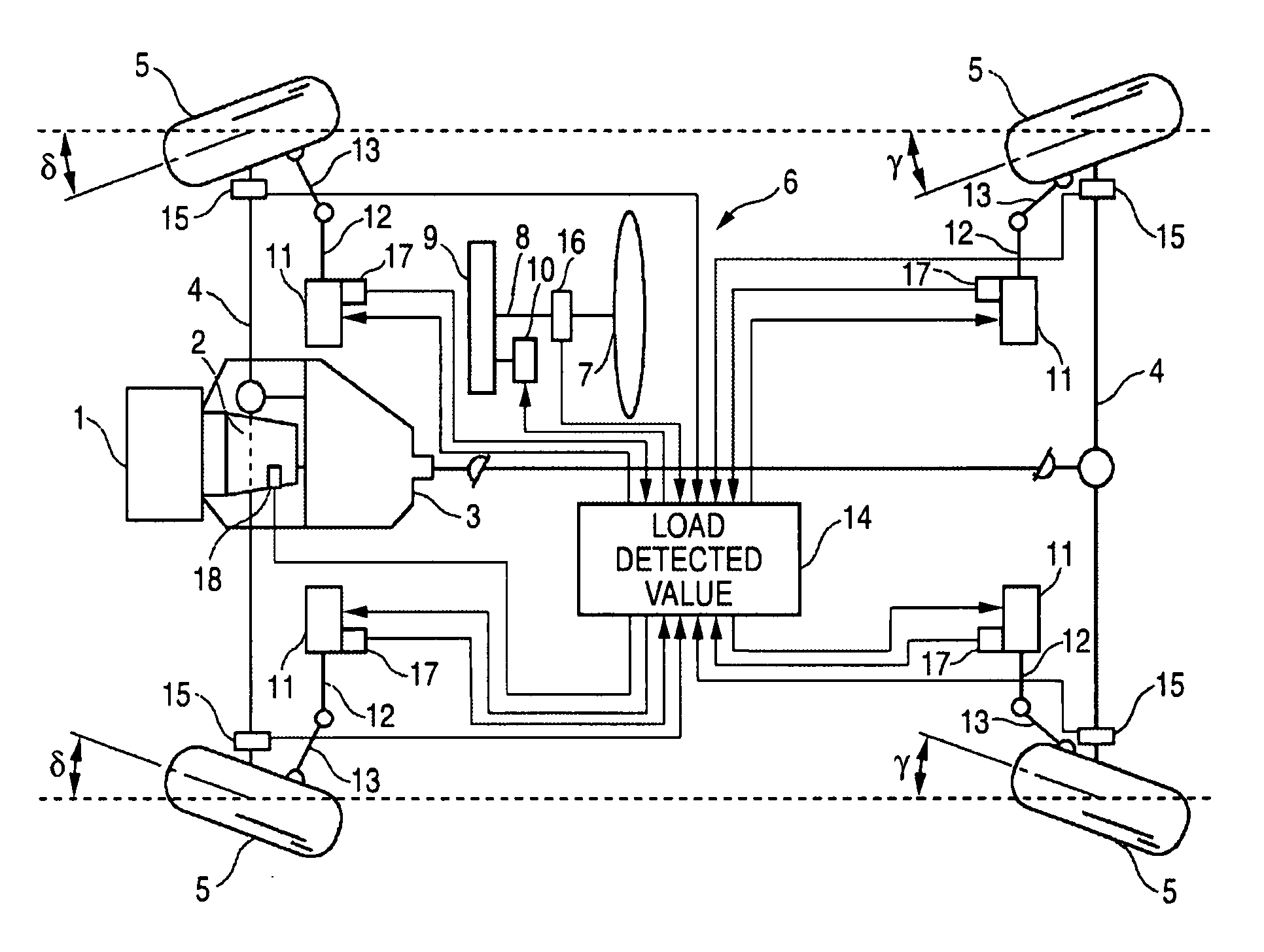
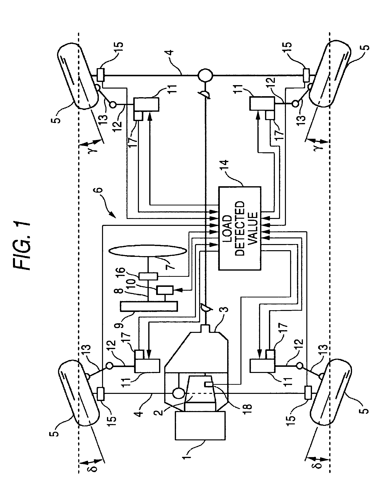
[0021]FIG. 1 is an explanatory diagram of a vehicle applying a steering apparatus according to an embodiment. The vehicle is a four-wheel drive car which is driven through both the front and rear wheels. Power from a crank shaft (not shown) of an engine 1 is transmitted to drive shafts (wheel axles) 4 for the front and rear wheels through an automatic transmission 2 and a center differential apparatus 3. When power is transmitted to the axles 4, a rotational torque is applied to wheels 5, whereby a driving force in the wheels 5 is generated.

[0022]A steering apparatus 6 of the four-wheel drive car adopts a four-wheel steering mechanism which can independently control the angle of steering (angle of wheel) of each of the wheels 5 provided in the vehicle. According to this embodiment, the four-wheel steering mechanism is a steer-by-wire mechanism in which the wheels 5 and the steering wheel 7 are mechanically separated, so that the relationship between the angle of the steering wheel a...

second embodiment

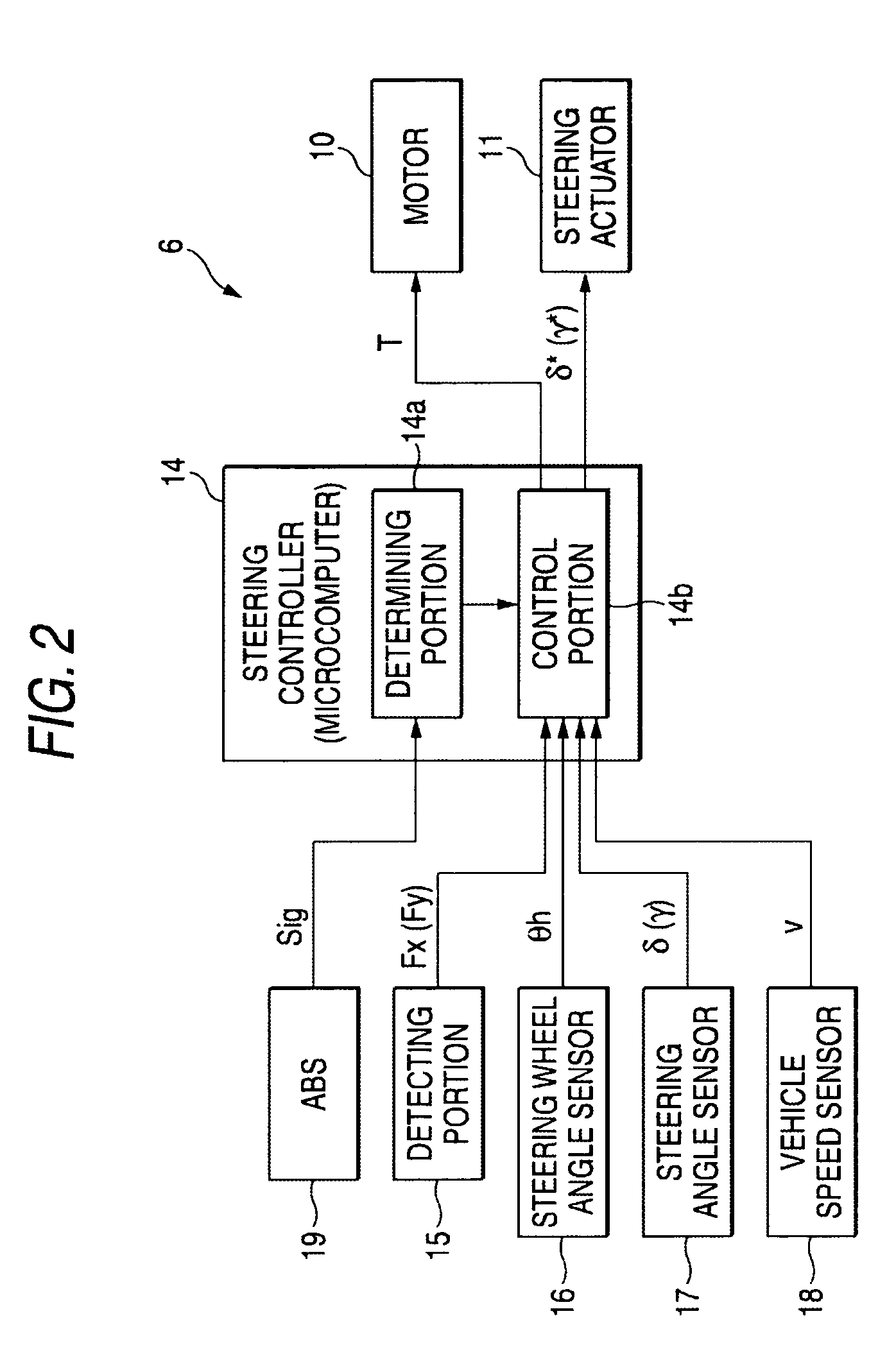
[0040]A second embodiment is different from the first embodiment with respect to the driving state in which the vehicle braking is permitted by the judgment portion 14a. Here, only differences between the embodiments will be described, since the system construction and system processing in the braking device according to the second embodiment are basically identical to those of the first embodiment. According to the first embodiment, the operation of the anti-lock brake is a requirement for permitting vehicle braking since the main object is to reduce braking distance and / or braking time on a graveled road, for example. On the other hand, the main object of this embodiment is emergency braking when a brake has a failure, and thus a failure in the ABS 19 is a condition for permitting vehicle braking. Therefore, a signal indicating a problem (failure and / or impaired function) is input from the ABS 19 to the steering controller 14. The signal may be a diagnosis code to be output from a...


PUM


Abstract

A wheel adjusting device can adjust separately the wheel angles of left and right wheels. A judgment portion which determines whether vehicle braking is to be permitted or not based on the driving state of the vehicle. A control portion controls the wheel adjusting device. More specifically, under conditions where the vehicle braking is permitted by the judgment portion, the control portion defines the wheel angles of the left and right wheels to be in opposite phase and adjusts the wheel angles in accordance with the braking force to be applied to the left and right wheels.

Description

CROSS REFERENCE TO RELATED APPLICATIONS[0001]The disclosure of Japanese Application No. 2004-175241 filed on Jun. 14, 2004 including the specification, drawings and abstract is incorporated herein by reference in its entirety.BACKGROUND OF THE INVENTION[0002]1. Field of the Invention[0003]The present invention relates to a vehicle steering apparatus and method.[0004]2. Description of the Related Art[0005]For example, German Patent Application Laid-Open No. 10121319 discloses an emergency braking apparatus for applying a braking force to wheels by controlling the angle of left and right wheels to be in opposite phase (opposite direction) when the brake system has a problem or when its function is limited. However, there are also normal brake systems for this purpose, such as JP-A-09-221019 which discloses an anti-lock brake system (ABS) for preventing wheels of a general brake from being locked during a braking operation in order to reduce the braking distance and / or braking time.[00...

Claims


Application Information

Patent Timeline
Patent Type & Authority Patents(United States)
IPC IPC(8): B60T8/62B62D6/00B60T7/00B60T7/10B60T8/00B60T8/176B60T8/1766B60T8/58B60T11/21B60W10/00B60W10/20B62D5/04B62D9/00B62D101/00B62D113/00
CPCB60T7/10B60T8/00B60T8/1766B60T11/21B62D9/007B60W10/184B60W10/20B60W40/10B60W10/119B60T2260/02B60W2510/20B60W2520/28
Inventor TSUKASAKI, YUICHIRO
Owner SUBARU CORP
Why Eureka
Try Eureka