
Apparatus and method for fusing voltage surge and transient anomalies in a surge suppression device

a technology of surge suppression device and surge surge, which is applied in the direction of emergency protective arrangement for limiting excess voltage/current, rope railways, etc., can solve the problems of equipment to operate improperly or completely fail, transient over voltage or voltage surge become even more problematic, and the effect of reducing overall lead length and lesser impedan

Active Publication Date: 2008-08-26
SURGE SUPPRESSION INC
View PDF17 Cites 27 Cited by
  • Summary
  • Abstract
  • Description
  • Claims
  • Application Information

AI Technical Summary

Benefits of technology

"The invention is an improved TVSS device that uses surge rated fuses and MOVs with thermal rated fuses to protect equipment from over voltage or current events. The device has advanced fusing circuitry that ensures the TVSS device can handle specific amounts of peak current surge without causing a catastrophic failure. The surge rated fuses are directly inserted onto the printed circuit board without the need for specialized fuse holders or solder tabs, reducing lead length and impedance. The close proximity of the thermal and surge rated fuses allows for quicker response time and improves the overall protection abilities of the TVSS device against catastrophic failure modes. The invention addresses the lower current abnormal over voltage catastrophic failure scenario and ensures the TVSS device can suppress the voltage surges and transients it is rated to handle and go off-line in those events that would normally cause catastrophic failure."

Problems solved by technology

Transient electrical anomalies include other types of electrical occurrences in the electrical line that are considered sub-cycle events which cause the equipment to operate improperly or completely fail (i.e., over-currents and the like).
Transient over voltages or voltage surges have become even more problematic in today's sophisticated electrical world wherein sensitive computerized equipment requires a constant and regulated supply voltage.
Since transient over voltages and voltage surges are very common, but difficult to predict, it is imperative to have a TVSS device on line at all times protecting the targeted piece of electrical equipment or circuit.
To leave the equipment unprotected can result in a devastating consequence wherein the equipment is temporarily brought off-line, severely damaged or completely destroyed.
This result could be detrimental to hospitals, police, fire and rescue units, the military and other critical functioning entities who can not afford to be “off-line” for any period of time.
It is understandable however, that even the best, most complex, most redundant TVSS devices are not one hundred percent effective against all electrical line surges and transient anomalies.
However, suppressing as many of these surges and transients as possible will most likely result in a longer life to the electrical equipment that the TVSS device is protecting and also help to minimize any possible “down-time”.
Although the desired result of voltage surge suppression may have been realized, the melting, burning or explosion of the MOV can cause other problems that must be addressed.
This new electrical conduction defeats the purpose of the TVSS device resulting in damage to the equipment that the TVSS device is meant to protect by letting through the voltage surge or transient which the TVSS was intended to suppress.
Further, unacceptable end of life conditions can cause damage to the equipment that the TVSS was intended to protect as well as surrounding equipment near the installation site of the TVSS.
Although this may be appropriate when employing small thermal fuses for each MOV, this would be more difficult if using larger current rated fuses.
For those circuits that require a significant level of transient voltage surge suppression, the size of such a device would not be acceptable for most applications with today's modern need for limited space requirements.
Further, even if the TVSS device could be made to be compact due to a minimal amount of surge suppression components being employed, and therefore a minimal number of fuses being employed, space requirements within the environment where the device is employed could still dictate that the device of this prior art reference is too large (i.e., the confined spacing requirements of a naval vessel).
Still further, the use of a current rated fuse for every MOV would most likely cause the TVSS device to constantly go off-line due to the fast acting response time of standard current rated fuses.
This of course would defeat the entire purpose of the TVSS device.
On the other hand, if only thermal fuses are employed, then the problems associated with a non-performing TVSS device that has reached its end of life due to high current abnormal over voltage conditions will still exist since the thermal fuses only work at the component level to take over-heated MOV components off-line.
Simply put, the use of thermal fuses only at the component level is inadequate for today's needs in transient voltage surge suppression technology.
However, the use of current rated fuses should not inhibit the TVSS device from doing its intended job of suppressing transients by taking the TVSS device off-line too quickly.

Method used


Image

  • Apparatus and method for fusing voltage surge and transient anomalies in a surge suppression device
  • Apparatus and method for fusing voltage surge and transient anomalies in a surge suppression device
  • Apparatus and method for fusing voltage surge and transient anomalies in a surge suppression device

Examples


Embodiment Construction

[0022]Throughout the following detailed description, the same reference numerals refer to the same elements in all figures.

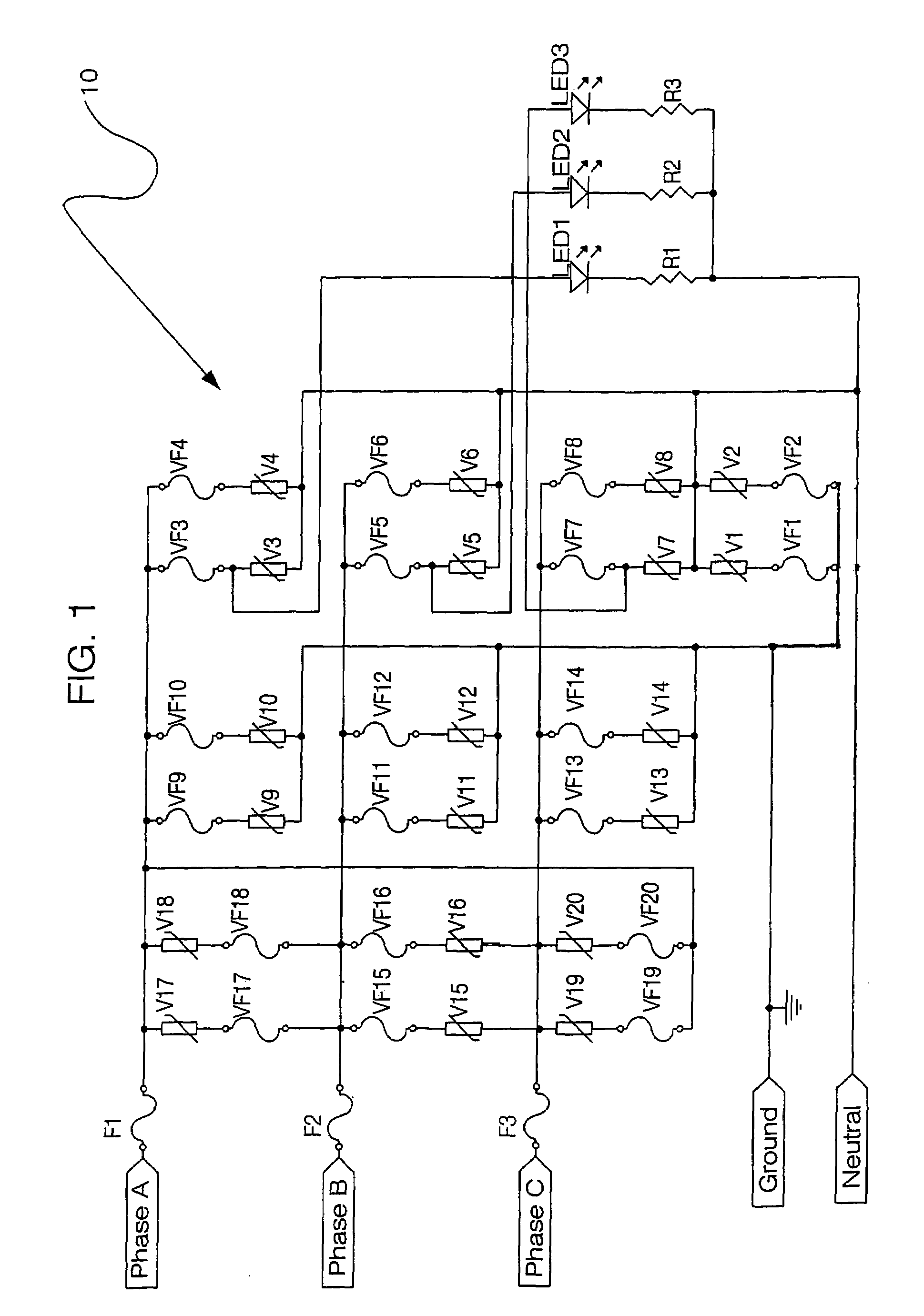
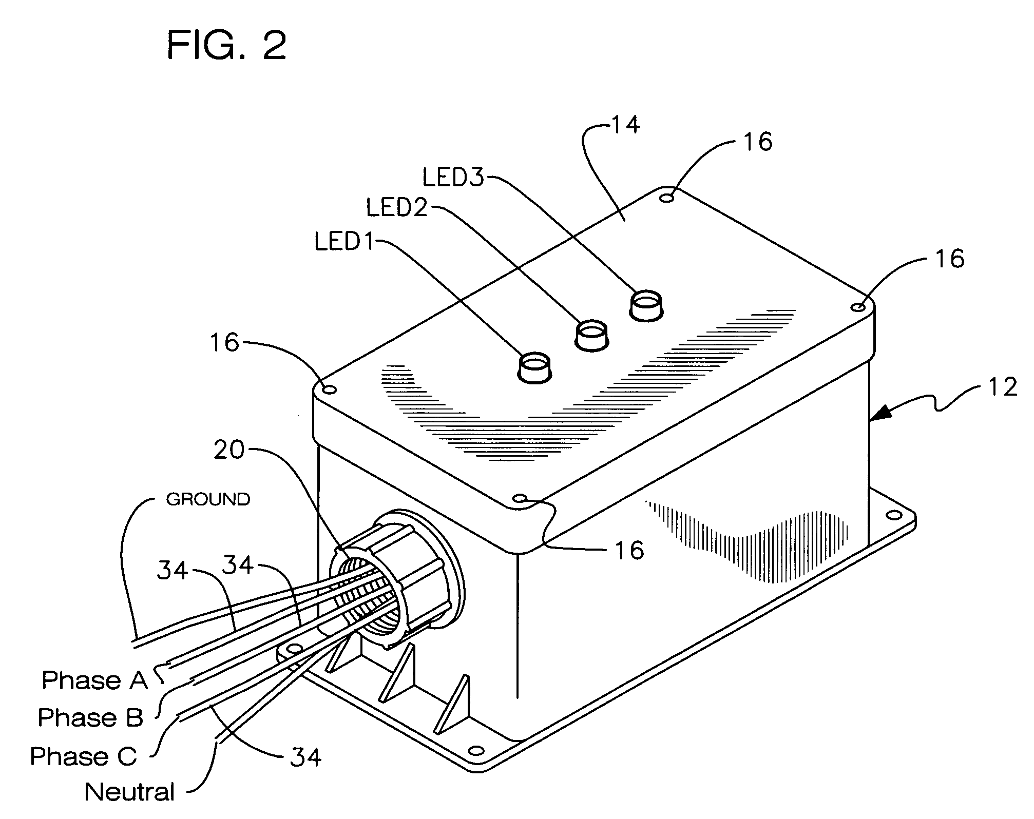
[0023]Referring to FIG. 1, an electrical schematic diagram is shown illustrating a fused transient surge suppression circuit 10 employed with a transient voltage surge suppression device of the present invention. As shown, circuit 10 employs a plurality of Metal Oxide Varistors (MOVs) V1-V20 arranged in three columns (one for each phase of a three phase line) but electrically coupled in parallel. It is understood that nothing herein limits the use of this novel circuit with either single or two phase lines. It is further understood that any number of MOVs or like surge suppression components can be employed per column. Also, the number of columns can vary dependent upon the modes of protection for the surge suppression application. FIGS. 1-3 illustrate a preferred embodiment wherein a three phase line is employed having Phase A, Phase B, Phase C, Neutral and Gro...


PUM


Abstract

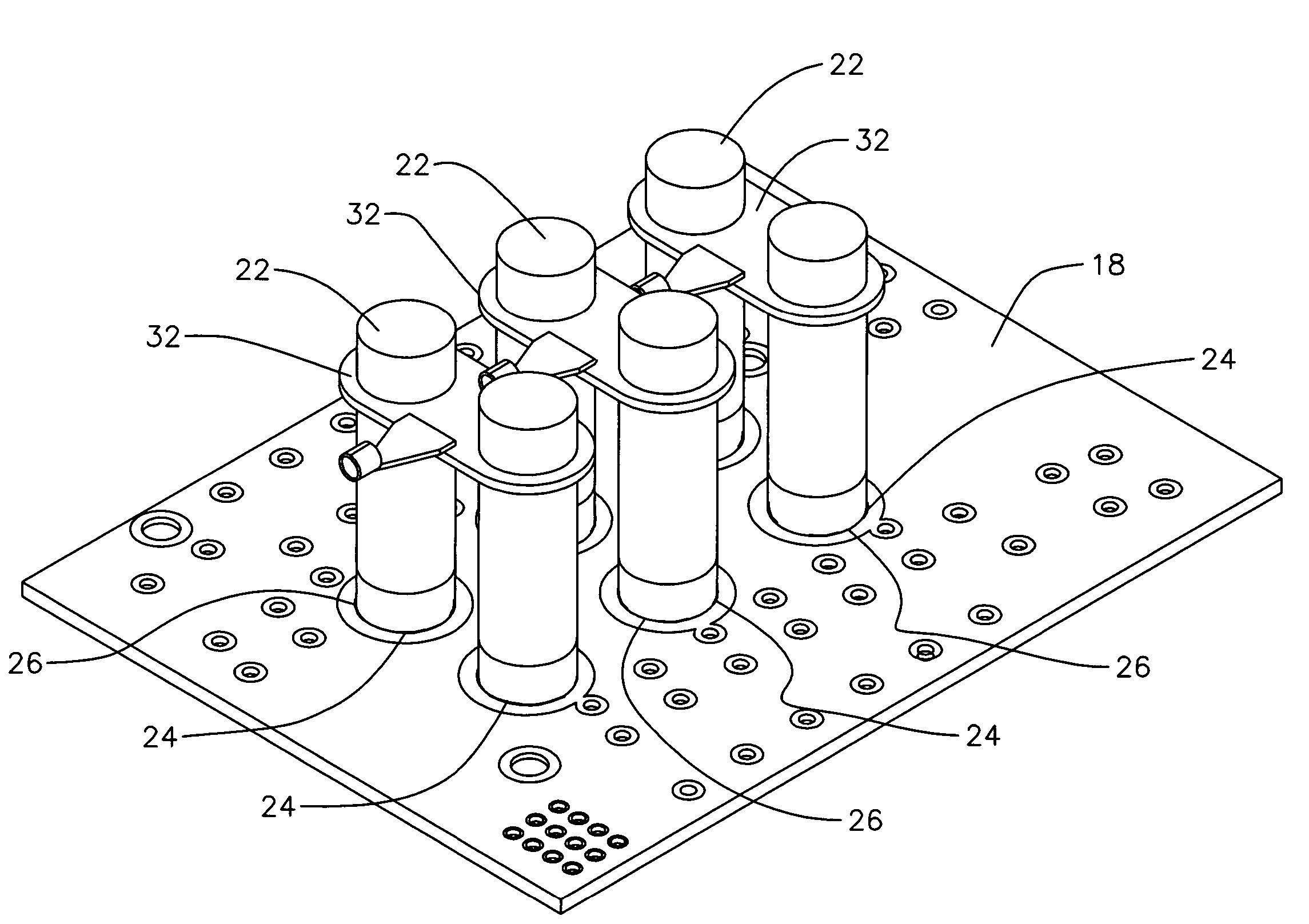
A circuit board is enclosed in a housing containing rows of metal oxide varistors. Multiple surge ferrule type fuses are soldered directly to circuit board holes between the rows of metal oxide varistors. A ring connector electrically connects pairs of fuses and an electrical conductor connects the ring connector to an electrical circuit to be protected.

Description

[0001]This application claims the benefit of U.S. Provisional Application No. 60 / 526,875 filing date Dec. 4, 2003.BACKGROUND OF THE INVENTION[0002]1. Field of the Invention[0003]The present invention relates to an apparatus and method for fusing surge protective device components on a printed circuit board designed to respond to and mitigate transient electrical anomalies and abnormal conditions to which the surge protective device may be subjected. More particularly, it relates to an apparatus and method for fusing surge protective device components thus protecting the circuit from both thermal and line level over-current conditions that can result in unacceptable end of life conditions for the transient voltage surge suppressor or surge protective device.[0004]2. Description of the Prior Art[0005]Transient Voltage Surge Suppression (TVSS) devices, also known as Surge Protective Devices (SPD), are well known in the prior art. TVSS devices are used with computers, other types of ele...

Claims


Application Information

Patent Timeline
Patent Type & Authority Patents(United States)
IPC IPC(8): H02H5/04H02H3/22H02H9/04
CPCH02H9/044H02H9/042
Inventor HOTCHKISS, RONALDHOTCHKISS, RICHARD
Owner SURGE SUPPRESSION INC
Learn More