
Support and radiation therapy system

support technology, applied in the field of support for a radiation therapy system, can solve the problems of reducing the precision of guiding the motion of the detector element, destroying or dying the tissue, and affecting the quality of radiation therapy, so as to reduce the precision of guiding the motion, increase the production cost disproportionately, and improve the effect of precision

Inactive Publication Date: 2008-08-26
SIEMENS HEALTHCARE GMBH
View PDF18 Cites 4 Cited by
  • Summary
  • Abstract
  • Description
  • Claims
  • Application Information

AI Technical Summary

Benefits of technology

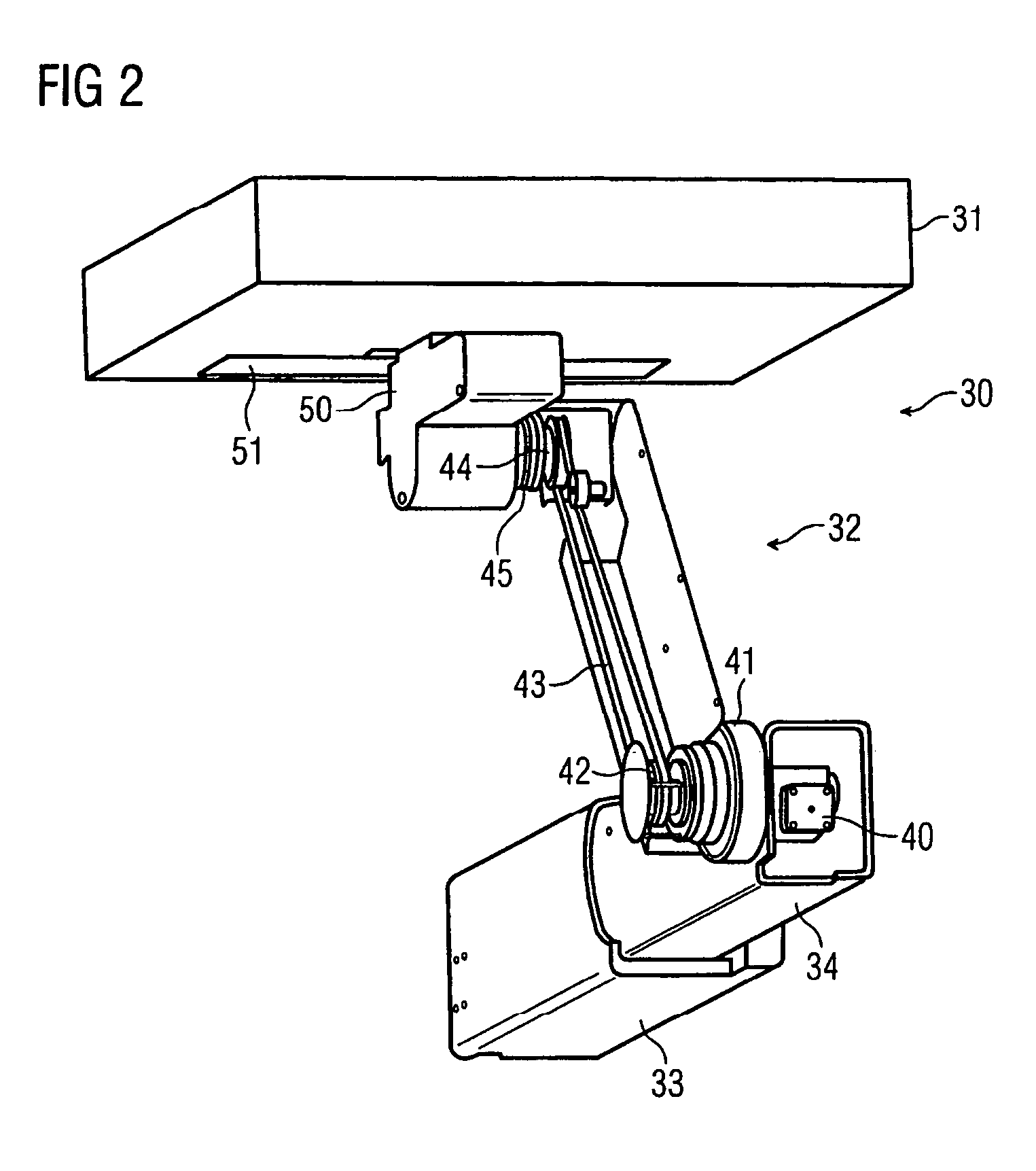
[0016]The kinematics of the arm and detector element with a motor and two contrary-operation gears provides a space-saving, flexible construction and precise guidance of the detector element. In this embodiment, only two rotary bearings are needed. The two rotary bearings are embodied with high precision.
[0017]In comparison, a conventional parallelogram kinematic embodiment, for example, is based on at least four rotary bearings, which would each have to be adapted to one another and in addition adapted to the parallelogram struts. The struts of the conventional parallelogram have to be adapted to one another as well. The many mutual dependencies of the conventional parallelogram reduce the precision in guiding the motion of the detector element and increase the production cost disproportionately. Depending on the dimensioning of the conventional parallelogram construction, the space required for the construction increases, in comparison to the single-strut arm. The radiation systems typically allow the rotation of the therapeutic and diagnostic rays about the isocenter, and as a result, the orientation of the arm and detector element is rotated as well. With the attendant change in the direction of gravity, increased demands in terms of precision of the guidance of motion are additionally made, which increases the effort and expense for construction and production. This expense is kept to a minimum by providing that only a small number of construction elements be provided for the kinematics.
[0018]In one embodiment, the motor is connected to the first gear by a shaft and to the second gear by a belt or chain. The shaft precisely guides the motion of the first gear. The belt or chain drive of the second gear is accurate and requires minimal structural effort and expense.

Problems solved by technology

These alterations can cause destruction or death of the tissue.
The positioning of the tissue, which takes place after determining the three-dimensional position, involves major possibilities of error, which can be a hindrance to exact positioning.
The various equipment components are disposed in the same beam path and may interfere with one another.
The many mutual dependencies of the conventional parallelogram reduce the precision in guiding the motion of the detector element and increase the production cost disproportionately.
With the attendant change in the direction of gravity, increased demands in terms of precision of the guidance of motion are additionally made, which increases the effort and expense for construction and production.

Method used


Image

  • Support and radiation therapy system
  • Support and radiation therapy system
  • Support and radiation therapy system

Examples


Embodiment Construction

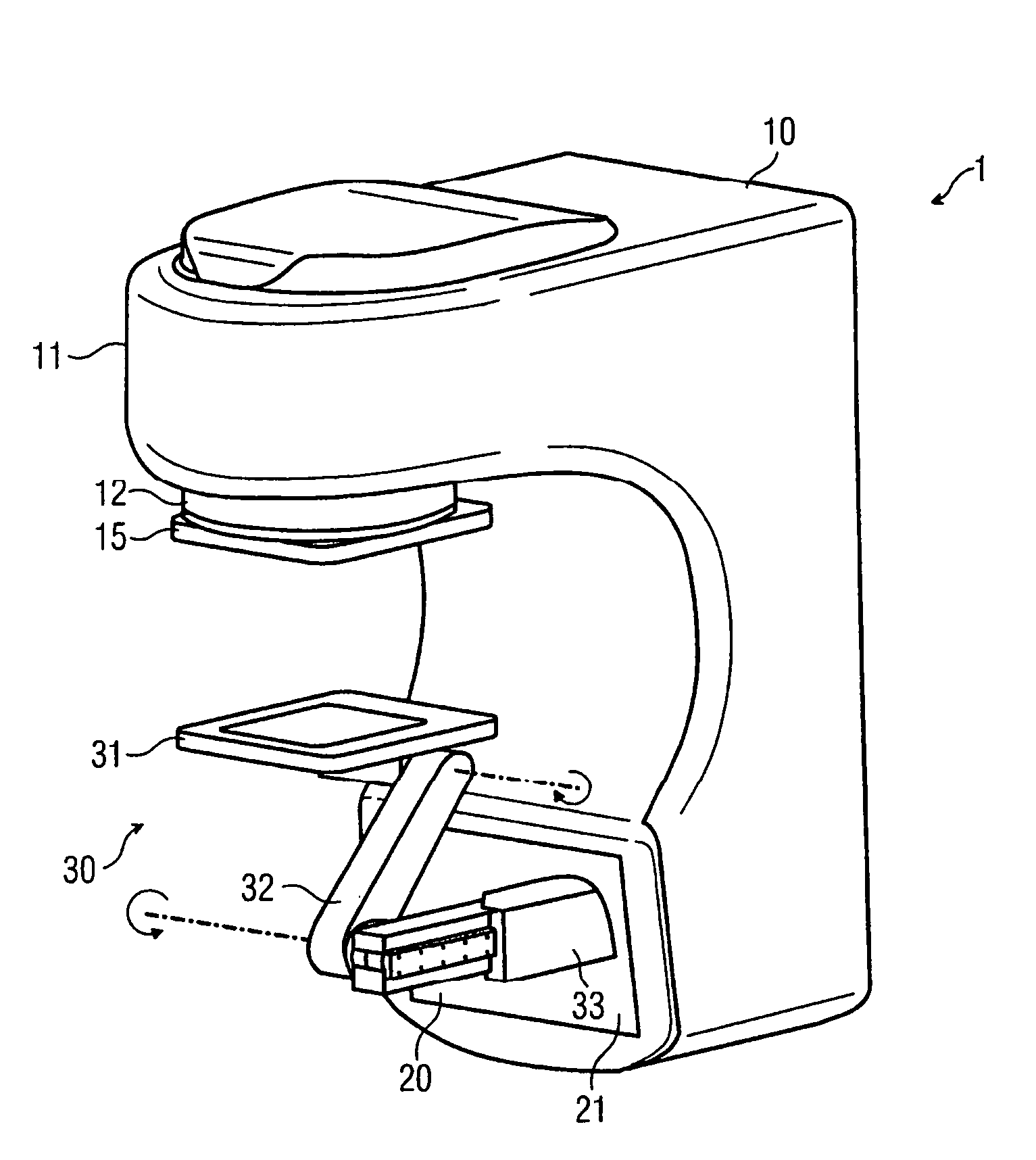
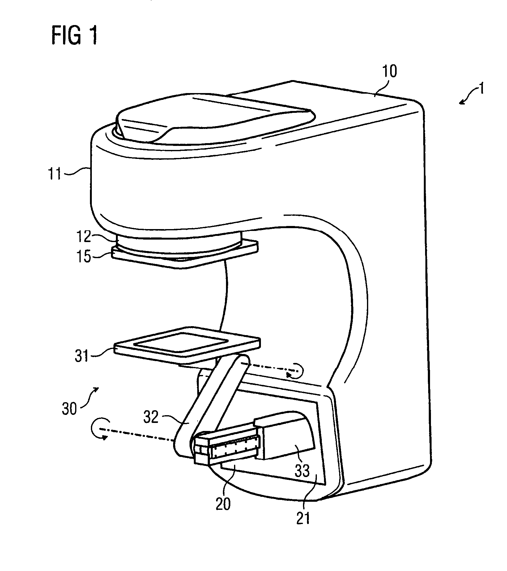
[0024]In one embodiment, as shown in FIG. 1, a radiation device 1 includes a gantry 10. The gantry 10 is supported rotatably about a horizontal axis and supports the essential functional components of the radiation device 1.

[0025]The gantry 10 has an emitter head 11, from which the therapeutic radiation is emitted, for example, in the direction of the MV detector 31 (downward in FIG. 1). A patient (not shown) to be irradiated is positioned on a patient positioning device (also not shown), with the body part that is to be irradiated located under the emitter head 11. A beam shaper 12 is provided on the emitter head 11. The beam shaper 12 shapes the contour of an irradiated beam. In alternate embodiments, the beam shaper 12 includes, for example, a focusing device, one or more diaphragms, and / or one or more collimators.

[0026]A kV detector 15 is disposed below the beam shaper 12. The kV detector 15 detects the X-radiation in the kV energy range. The kV detector 15 makes it possible to ...


PUM


Abstract

A support and radiation therapy system is provided. The support includes an elongated support arm that is longitudinally adjustable. A first arm is rotatable in the support arm about a first axis that is perpendicular to the support arm. A flat detector is rotatable in the first arm about a second axis that is parallel to the first axis. The detector is essentially parallel to the support arm. A motor is operative to drive the rotation of the first arm. A first gear is operative to rotate the first arm and is connected to the motor. A second gear is operative to rotate the detector and is connected to the motor. The second gear is operative to rotate contrary to the first gear.

Description

[0001]The present patent document claims the benefit of the filing date of DE 10 2005 048 391.7, filed Oct. 10, 2005.BACKGROUND[0002]1. Field[0003]The present embodiments relate to a support for a radiation therapy system.[0004]2. Related Art[0005]Radiation systems are used in medical therapy for irradiating diseased tissue, for example, tumor tissue. Suitable radiation types of therapy include, for example, high-energy X-radiation in the megavolt range; lightweight particle radiation (i.e. electrons or positrons or protons); and heavy particle radiation (i.e. oxygen or carbon ions). Because of the radiation, the bonds of the living tissue are destroyed or atoms are ionized. These alterations can cause destruction or death of the tissue. Although this effect is intended with regard to the tumor tissue or diseased tissue, this effect must be avoided in healthy tissue. In a desired radiation system, the radiation dose administered to diseased tissue should be increased and the radiati...

Claims


Application Information

Patent Timeline
Patent Type & Authority Patents(United States)
IPC IPC(8): A61N5/10H01J31/50H05G1/64
CPCA61N5/1049A61N2005/1054A61B6/00F16M11/18F16M11/38
Inventor FADLER, FRANZ
Owner SIEMENS HEALTHCARE GMBH
Learn More