Fluid filled vibration damping device

a technology of vibration damping and fluid filling, which is applied in the direction of shock absorbers, machine supports, jet propulsion mountings, etc., can solve the problems of noise and vibration, noise that is unfavorable to the operator, so as to achieve the effect of attenuating impact energy, reducing noise and vibration, and compactness

Active Publication Date: 2008-09-02
SUMITOMO RIKO CO LTD
View PDF19 Cites 19 Cited by
  • Summary
  • Abstract
  • Description
  • Claims
  • Application Information

AI Technical Summary

Benefits of technology

[0010]It is therefore one object of this invention to provide a fluid filled vibration damping device equipped with a hydraulic absorption mechanism, which alleviates impact when the inner surface of the housing space of the movable late forming the hydraulic absorption mechanism is struck, thereby being capable of rapidly reducing disagreeable noise and the like caused by such strikes.

Problems solved by technology

However, during rapid pressure fluctuations in the pressure receiving chamber upon the input of vibrations of greater amplitude in this type of hydraulic absorption mechanism, the movable panel strikes the inner surface of the housing space.
The impact of the movable panel striking the surface tends to result in noise and vibration.
If used as an automobile engine mount, for example, the noise will sound disagreeable to the operator when the engine is cranked or while driving over bumps, detracting from the driving experience.
Although this type of small protrusion is effective against low energy strikes, it is not very effective during rapid and extensive pressure fluctuations in the pressure receiving chamber, and another way of dealing with this problem is needed.

Method used


Image

  • Fluid filled vibration damping device
  • Fluid filled vibration damping device
  • Fluid filled vibration damping device

Examples


first embodiment

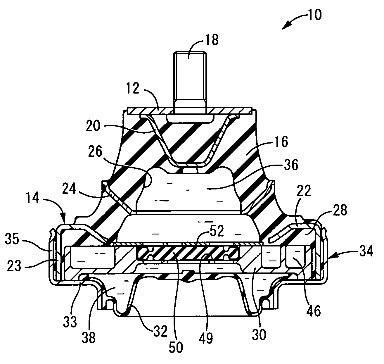
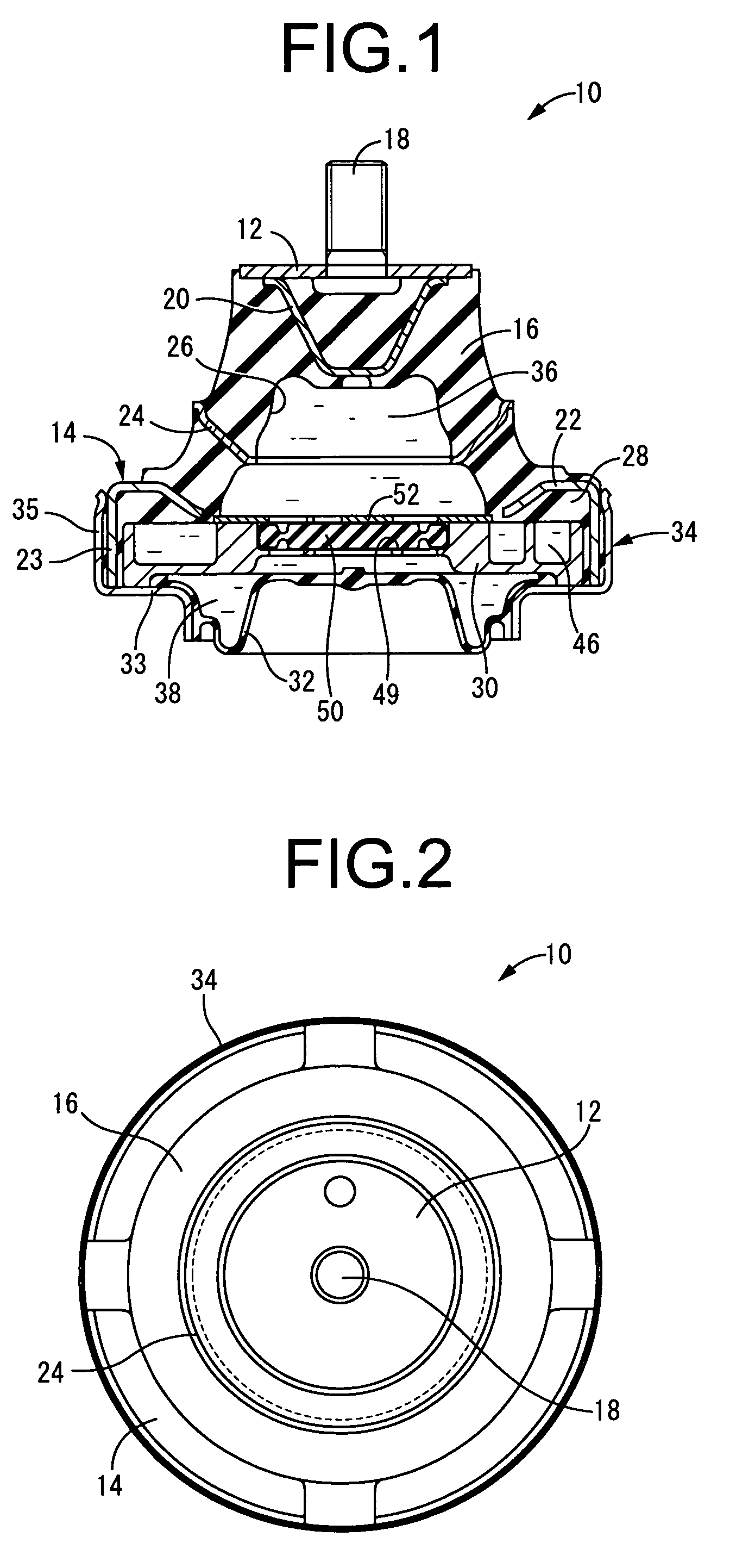
[0060]FIGS. 1 and 2 illustrate an automobile engine mount 10 in the invention. This engine mount 10 has a construction wherein a metallic first mounting member 12 and a metallic second mounting member 14 are elastically connected by means of a main rubber elastic body 16. The engine mount 10 is such that the first mounting member 12 is attached to a power unit, while the second mounting member 14 is attached to a n automobile body, so that the power unit is supported in a vibration damping manner in cooperation with other engine mounts and the like (not shown) relative to the body. The first mounting member 12 and second mounting member 14 are vertically (in FIG. 1) displaced a certain distance toward each other as the main rubber elastic body 16 is elastically deformed by the input of the shared load of the power unit onto the mount 10 which has been set up in the manner described above, and the primary vibrations which are to be damped are input in generally the vertical direction...

second embodiment

[0109]FIG. 14 illustrates the invention in the form of an engine mount in which the movable rubber plate 50 is set up in the housing space 49 in a state or pressure in the panel thicknesswise direction. In the engine mount 100 illustrated in FIG. 14, a power unit attached to a first mounting member 102 is elastically supported in a suspended state by the vehicle body attached to a second mounting member 104, and is mounted with the vertical direction in FIG. 14 being in the generally vertical direction.

[0110]More specifically, in the engine mount 100 in this embodiment, the second mounting member 104 having a large diameter cylindrical shape is disposed at a distance on the outer peripheral side from the first mounting member 102. The first mounting member 102 is disposed on the same center axis in the bottom opening of the second mounting member 104, and the first mounting member 102 and second mounting member 104 are elastically linked by a main rubber elastic body 106. The main r...


PUM


Abstract

A fluid filled vibration damping device wherein a first and second mounting member are connected by a main rubber elastic body, a pressure receiving chamber partially formed by the rubber elastic body and an equilibrium chamber partially formed by a flexible film are formed on either side of a partition member supported by the second mounting member, an orifice passage is formed for permitting a fluid communication between the pressure receiving chamber and equilibrium chamber communicate both having a non-compressible fluid; and a movable rubber plate is housed in a housing space so that minute pressure fluctuations in the pressure receiving chamber can be absorbed by the equilibrium chamber by means of the movable rubber plate. The movable rubber plate includes at least partially a corrugated part expanding generally a form of a corrugated panel by means of continuous depressions and protrusions.

Description

INCORPORATED BY REFERENCE[0001]The disclosure of Japanese Patent Application No. 2004-286205 filed on Sep. 30, 2004 including the specification, drawings and abstract is incorporated herein by reference in its entirety.BACKGROUND OF THE INVENTION[0002]1. Field of the Invention[0003]The present invention relates to a vibration damping device applicable as an engine mount for use in an automotive vehicle, for example, and in particular to a fluid filled vibration damping device in which damping effects are obtained based on flow action of a non-compressible fluid sealed in the interior.[0004]2. Description of the Related Art[0005]A fluid filled vibration damping is known as one type of damping connectors or damping supports mounted between members forming a vibration transmission system. JP-Y-4-33478 shows one example of the fluid filled vibration damping device. This type of damping device typically includes: a first and a second mounting member elastically connected together by a ru...

Claims


Application Information

Patent Timeline
Patent Type & Authority Patents(United States)
IPC IPC(8): F16F13/10
CPCF16F13/106B60K5/1266F16F13/105
Inventor HASEGAWA, KOICHIYOSHII, NORIAKI
Owner SUMITOMO RIKO CO LTD
Why Eureka
Try Eureka