Multilayer microfluidic device

a microfluidic device and multi-layer technology, applied in the field of microfluidic devices, can solve the problems of elastomeric microfluidic structures that can buckle or collapse, and the time and power required for fabrication are relatively high,

Active Publication Date: 2008-09-02
THE BOARD OF TRUSTEES OF THE LELAND STANFORD JUNIOR UNIV
View PDF24 Cites 69 Cited by
  • Summary
  • Abstract
  • Description
  • Claims
  • Application Information

AI Technical Summary

Benefits of technology

[0009]The present invention also provides methods of fabricating multilayer microfluidic devices. With this method, a layer of elastomer is dry etched on a rigid support layer to create at least one opening in the elastomeric layer. Next, a rigid layer is photolithographically patterned on a rigid substrate layer to create at least one opening in the rigid layer. The openings in the dry-etched elastomeric layer and the photolithographically patterned rigid layer are then aligned to define microfluidic structures. The microfluidic structures are then formed by binding the dry-etched elastomeric layer to the photolithographically patterned rigid layer, preferably by spontaneous adhesion at room temperature. Preferably, the photolithographically patterned rigid layer and the dry-etched elastomeric layer are designed to allow relative shifts of at least about two microns in each in-plane direction during alignment while maintaining the functionality of the microfluidic structures. This error tolerant alignment process overcomes the difficulty in interfacing and aligning layers made of two different materials.

Problems solved by technology

These structures have stable surface chemistry and hydrophilicity, but suffer from several drawbacks.
For example, the time and power required for fabrication are relatively high, and planarization and high heat are required for sealing the structures to a substrate.
However, elastomeric microfluidic structures can buckle or collapse when pressure, vacuum, or topside forces are applied.
Thus, ex-situ fabricated elastomeric microfluidic structures cannot be precisely aligned to a substrate using standard alignment tools.
In addition, the process of soft lithography has problematic issues pertaining to separating the precision cast elastomeric microfluidic structures from the mold.

Method used


Image

  • Multilayer microfluidic device
  • Multilayer microfluidic device
  • Multilayer microfluidic device

Examples


Embodiment Construction

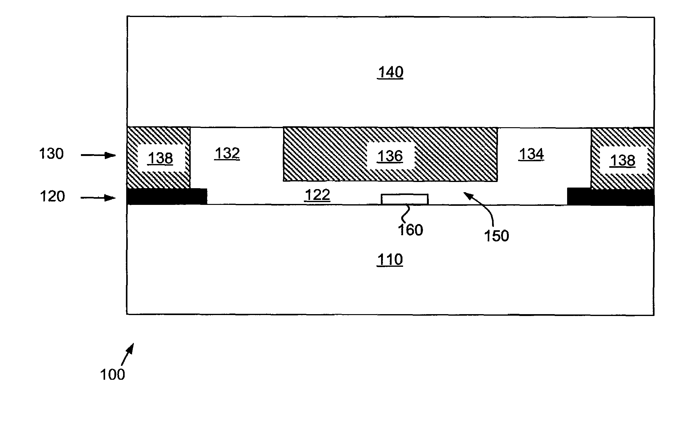
[0030]FIG. 1 shows a schematic cross-section of a microfluidic device 100 according to the present invention. Microfluidic device 100 has four layers, including a rigid substrate layer 110, a patterned rigid layer 120, a patterned elastomeric layer 130, and a rigid support layer 140. In addition, the microfluidic device has a sensor 160. The patterned rigid layer 120 has at least one opening 122. Preferably, this opening extends through the entirety of patterned rigid layer 120, as shown in FIG. 1. The patterned elastomeric layer 130 also has at least one opening, such as openings 132 and 134. Preferably, this opening(s) extends through the entirety of patterned elastomeric layer 130, as shown in FIG. 1. Also preferably, the height of the opening(s) in the elastomeric layer can range between being a fraction of the width of the opening(s) and about two times the width of the opening(s). The alignment of openings 122, 132, and 134, define microfluidic structures, such as sensing chan...


PUM

PropertyMeasurementUnit
thicknessaaaaaaaaaa
thicknessaaaaaaaaaa
thicknessaaaaaaaaaa

Abstract

The present invention provides microfluidic devices constructed from four layers. The layers include a rigid substrate layer, a patterned rigid layer having thickness t, a patterned elastomeric layer having thickness greater than t, and a rigid support layer. Microfluidic structures in the devices are defined by the alignment of openings in the patterned rigid layer and the patterned elastomeric layer. The rigid support layer, rigid substrate layer, and patterned rigid layer may be made of any rigid material, including but not limited to plastic or silicon-containing materials, such as glass, quartz, or SiO2-coated materials. Similarly, the patterned elastomeric layer may be made of any elastomeric material, including but not limited to polydimethylsiloxanes, polymethylmethacrylates, perfluoropolyethers, or combinations thereof. Microfluidic devices according to the present invention may include sensors or sensor arrays. The microfluidic devices are fabricated using the provided error-tolerant alignment, biocompatible process.

Description

CROSS-REFERENCE TO RELATED APPLICATIONS[0001]This application is a continuation in part of U.S. application Ser. No. 11 / 297,883, filed Dec. 9, 2005, now abandoned which claims priority from U.S. Provisional Patent Application No. 60 / 635,126, filed Dec. 10, 2004, and which is a continuation in part of U.S. patent application Ser. No. 11 / 128,105, filed May 11, 2005, which claims priority from U.S. Provisional Patent Application No. 60 / 570,672, filed May 12, 2004, all of which are incorporated herein by reference.STATEMENT REGARDING FEDERALLY SPONSORED RESEARCH OR DEVELOPMENT[0002]This invention was made in part with government support under grant no. SPO 26739 awarded by the U.S. Navy. The government has certain rights in this invention.FIELD OF THE INVENTION[0003]The present invention relates generally to microfluidic devices. More particularly, the present invention relates to microfluidic devices having a rigid substrate layer, a patterned rigid layer, a patterned elastomeric layer...

Claims


Application Information

Patent Timeline
Patent Type & Authority Patents(United States)
IPC IPC(8): B01L3/02G01N15/06G01N33/00G01N33/48
CPCB01L3/502707B01L9/527B01L2200/0689B01L2200/12B01L2300/0636B01L2300/0816Y10T436/11B01L2400/0415B01L2400/043B81B2201/058Y10T436/25Y10T436/2575B01L2300/123
Inventor OSTERFELD, SEBASTIAN JWANG, SHAN X.
Owner THE BOARD OF TRUSTEES OF THE LELAND STANFORD JUNIOR UNIV
Why Eureka
Try Eureka