Lateral piezoelectric microelectromechanical system (MEMS) actuation and sensing device

a microelectromechanical system and piezoelectric technology, applied in piezoelectric/electrostrictive/magnetostrictive devices, piezoelectric/electrostriction/magnetostriction machines, electrical apparatus, etc., can solve the problem of limiting the out-of-plane movement of piezoelectric mems, and reducing the effective in-plane actuation

Inactive Publication Date: 2008-09-02
UNITED STATES OF AMERICA THE AS REPRESENTED BY THE SEC OF THE ARMY
View PDF9 Cites 32 Cited by
  • Summary
  • Abstract
  • Description
  • Claims
  • Application Information

AI Technical Summary

Benefits of technology

[0013]The connection beams provide both mechanical and electrical connection between the actuation beams and, although are piezoelectrically active, do not contribute to the deformation of the device. The actuation beams comprise two sets of the second electrodes. Moreover, the sets of second electrodes comprise an extensional electrode and a contraction electrode. Only one of the two sets of second electrodes is electrically active when the device is in use. The other set of second electrodes serves to provide a mechanically beneficial symmetry to the system that allows for greater actuation sensitivity. Without this symmetry, the generated moment arm (δ) would partially reside out of the intended plane of bending (x-y); diminishing the effective in-plane actuation. Furthermore, the end effector is attached to residual stress deformation mitigation springs, which are adapted to prevent out-of-plane stress deformation of the actuator and to restrict the translational motion of the end effector to be uniaxial within the x-y plane.
[0014]The embodiments of the invention allow for piezoelectric actuation and sensing that utilizes two additional translational degrees of freedom by permitting motion in the x-y plane. This capacity permits the developments of entirely new classes of piezoelectric MEMS devices. The various actuator devices provided by the several embodiments of the invention function such that one of the sets of top electrodes are actuated asymmetrically with respect to the x-z plane (the origin is located at the center of the beam). For a structure that is symmetric about the midplane of the piezoelectric layer, this results in a piezoelectrically induced bending moment arm (δ) that lies in the x-y plane. The induced bending thus occurs in the x-y plane (i.e. the lateral direction). The embodiments of the invention effectively rotate the piezoelectric moment arm (δ) from the standard case, residing in the x-z plane, into the x-y plane; thus changing the plane of bending. The x-z plane may be thought of as a first plane transverse to the x-y plane (second plane).

Problems solved by technology

However, piezoelectric MEMS out-perform electrostatic MEMS actuators in out-of-plane (vertical) displacements in terms of attainable range, power consumption, and voltage level.
However, currently, piezoelectric MEMS are limited to out-of-plane motion while electrostatic MEMS excels at in-plane actuation.
However, such a structure does not facilitate in-plane bending.
However, this conventional design generally cannot be implemented at the MEMS scale without modifications to account for the MEMS specific problems of residual stress deformation and thin film piezoelectric electroding requirements.
As such, the lack of piezoelectric actuators with additional spatial degrees of freedom has limited the scope of possible piezoelectric MEMS devices to date.

Method used


Image

  • Lateral piezoelectric microelectromechanical system (MEMS) actuation and sensing device
  • Lateral piezoelectric microelectromechanical system (MEMS) actuation and sensing device
  • Lateral piezoelectric microelectromechanical system (MEMS) actuation and sensing device

Examples


Embodiment Construction

[0036]The embodiments of the invention and the various features and advantageous details thereof are explained more fully with reference to the non-limiting embodiments that are illustrated in the accompanying drawings and detailed in the following description. It should be noted that the features illustrated in the drawings are not necessarily drawn to scale. Descriptions of well-known components and processing techniques are omitted so as to not unnecessarily obscure the embodiments of the invention. The examples used herein are intended merely to facilitate an understanding of ways in which the embodiments of the invention may be practiced and to further enable those of skill in the art to practice the embodiments of the invention. Accordingly, the examples should not be construed as limiting the scope of the embodiments of the invention.

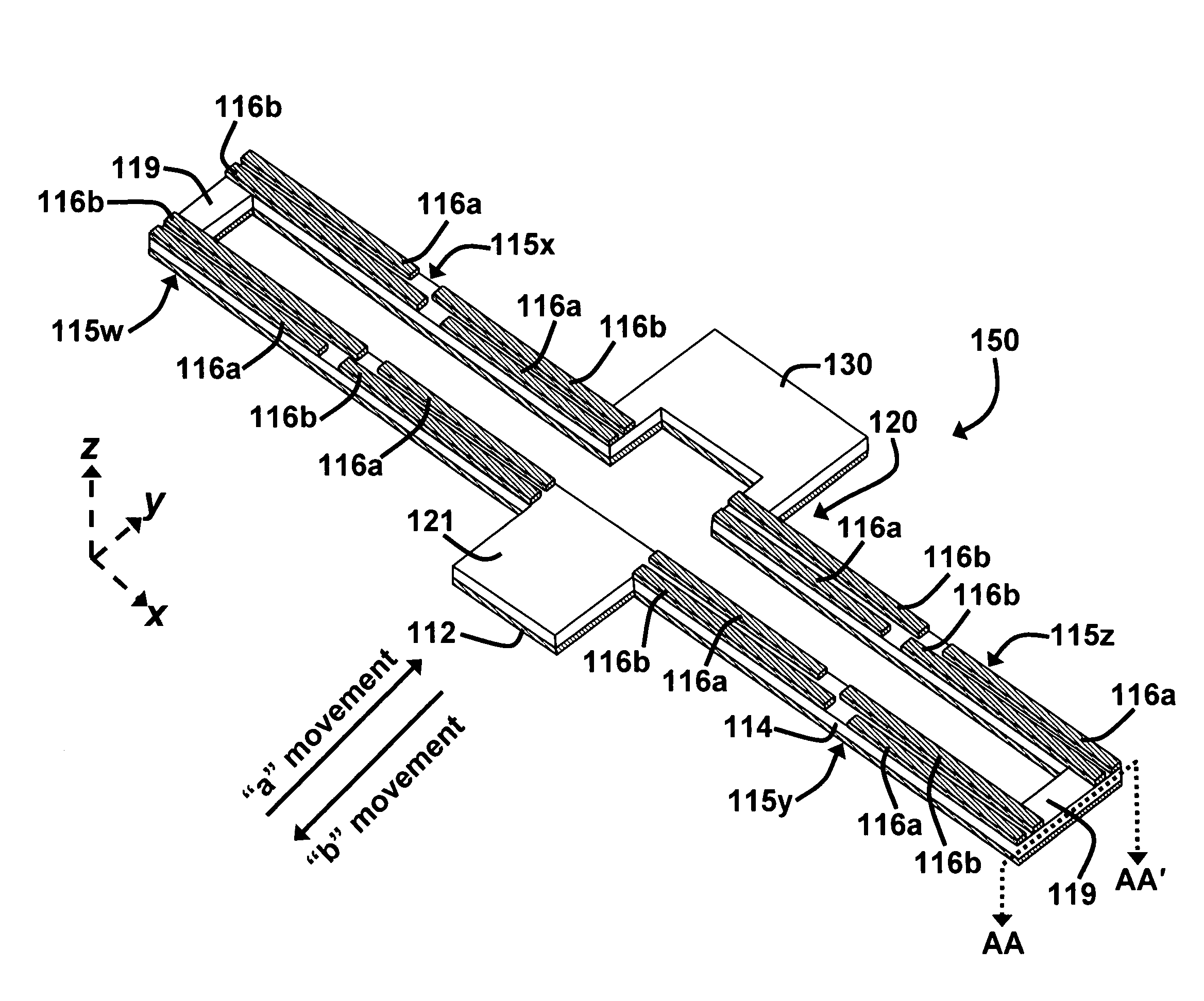
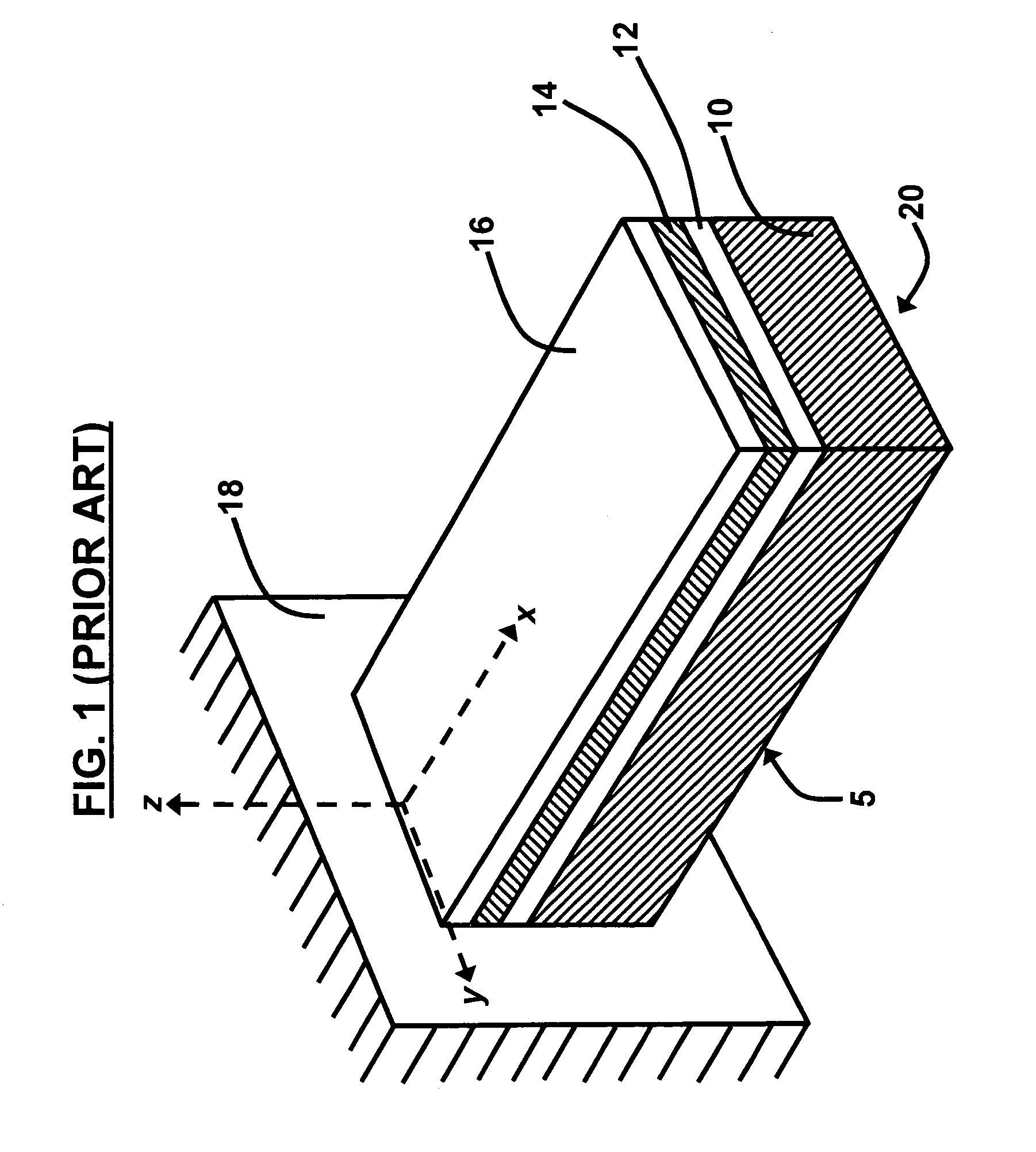
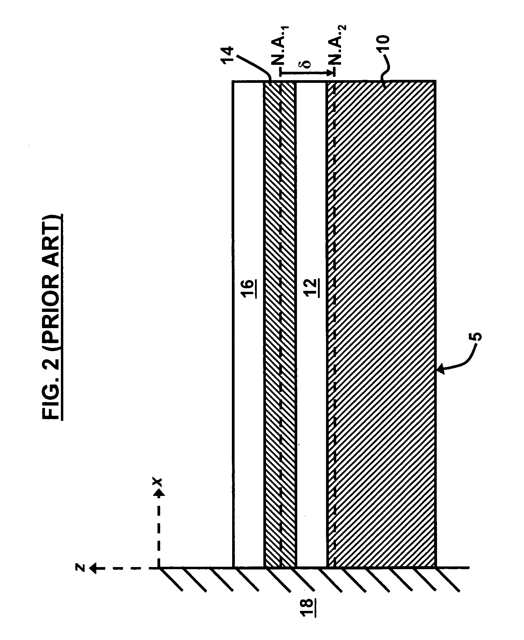
[0037]As mentioned, there is a need for a novel piezoelectric MEMS actuator / sensor device in which induced / sensed bending of the MEMS structure ...


PUM


Abstract

A microelectromechanical system (MEMS) device comprises a substrate; an anchored end connected to the substrate; a free end comprising an end effector opposite to the anchored end; a spring attached to the end effector; multiple actuation beams; multiple connection beams adapted to connect the multiple actuation beams to one another; and an actuator / sensor comprising a first electrode; a piezoelectric layer over the first electrode; and a set of second electrodes over the piezoelectric layer, wherein the set of second electrodes being defined by a transverse gap therebetween. Each of the multiple actuation beams comprises two sets of the second electrodes. The set of second electrodes comprise an extensional electrode and a contraction electrode. One of the sets of second electrodes is actuated asymmetrically with respect to a first plane resulting in a piezoelectrically induced bending moment arm in a lateral direction that lies in a second plane.

Description

GOVERNMENT INTEREST[0001]The embodiments of the invention described herein may be manufactured, used, and / or licensed by or for the United States Government.BACKGROUND OF THE INVENTION[0002]1. Field of the Invention[0003]The embodiments of the invention generally relate to microelectronic systems, and more particularly to microelectromechanical systems (MEMS) and MEMS actuation and sensing technology.[0004]2. Description of the Related Art[0005]MEMS devices are micro-dimensioned machines manufactured by typical integrated circuit (IC) fabrication techniques. The relatively small size of MEMS devices allows for the production of high speed, low power, and high reliability mechanisms. The fabrication techniques also allow for low cost mass production. MEMS devices typically include both electrical and mechanical components, but may also contain optical, chemical, and biomedical elements.[0006]There are a number of actuation and sensing technologies utilized in MEMS; the most common ar...

Claims


Application Information

Patent Timeline
Patent Type & Authority Patents(United States)
IPC IPC(8): H03H9/00
CPCH01L41/096H01L41/0953H10N30/2044H10N30/2045
Inventor PULSKAMP, JEFFREY S.
Owner UNITED STATES OF AMERICA THE AS REPRESENTED BY THE SEC OF THE ARMY
Why Eureka
Try Eureka